Merging similar surfaces

Hi all,
newbie here - I have the situation where I have lots of surfaces coming from a cadquery representation, that I export as stl-representations and then remesh using mmgs. This works fine, except that in rather a lot of cases I have overlapping/touching surfaces. For my end use case (neutron transport) I need my surfaces to be exactly identical, if they are touching. Inside cadquery I can split the surfaces fine, but the remeshing process makes things unequal again.

Is there for instance a way where one can remesh partial meshes and stitch that together with an already “finished representation”?
Or can one check the generated mesh-surfaces for similarity?
Or does anyone have other ideas.

I do realize this is a somewhat vague question, but I am looking for ideas.
cheers
Erik

Hi,

I hope that I have well understood your issue (if you realize that it is not the case, do not hesitate to attach picture to illustrate your description, it can be really helpful).

In Mmg you can set required entities to forbid remeshing locally. In your case I guess that you want to preserve at least some edges and probably some triangles too.
You have an example of the syntax and of the behaviour of remeshing in presence of required entities here : Localized Remesh.

To preserve edges (resp. vertices) instead of triangles, you just have to replace the keyword by the good one and to use the RequiredEdges (resp RequiredVertices) keyword.

I hope that it will work for your test case.

Best Regards,
Algiane

Hi,
Thanks for the reply - I think this is exactly what I would like to do.

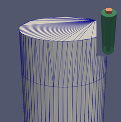
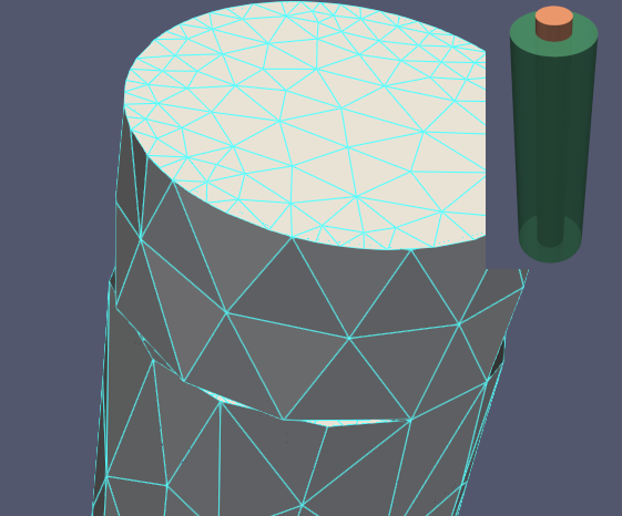
to test matters I’ve created a test-geometry with a rod inside a pipe, where the surfaces are touching (i.e. the outer cylinder of the rod touches the inside surface of the pipe. I can generate stl-representations of these using cadquery, where the touching surfaces are split into separate faces where they coincide. In the example case this cuts the inner cylinder into three regions as can be seen in fig 1. These meshes are not very good as the triangles are very long and thin - this is where mmg comes in. I’d like to be able to remesh the surfaces but keep the edge-points intact, so they would always match up and not create spurious features at the edges of two objects as can be seen in fig 2. From what I can understand this is exactly what RequiredEdges allows me to do. Did I get that right? If so, all I need to do is figure out how to supply this information to mmgs.
cheers - and thanks again
Erik


Fig. 1.
fig2_overlaps
Fig. 2.

HI again,
I can’t get this to do what I want - at present it makes no diffference whatsoever whether I specify RequiredEdges or not. To the extent that the produced files are identical. This may be a product of the fact that the input .stl-files do not have any edge-information My procedure is (at present): I convert the .stl-file to a mesh file using gmsh as a filter, then I re-mesh these using mmgs and this unfortunately produces the kind of artefacts that we see above. What I’d really like to do is to get the edges to be like in fig 1., where they share vertices. Much like the isolines in the 2nd teapot example here: Implicit domain meshing – Mmg Platform
I’ll look into that as well

Hi,

So you have added the RequiredEdges keyword in the .mesh file generated by Gmsh ?
Is it possible to attach this file so I can try to figure out what happens?

In practice and from a physical point of vue, do you really need 2 different pieces of surfaces (leading to duplicated interface edges ) or is it suitable to have one piece of surface (with different “materials”) with unique interface edges? In the last case, it would make more sense (physically at least) to solve the issue of the double edges (because providing unique surface/edges will allow you conforming remeshing). Freezing the edges is a roundabout way to not see that your mesh don’t describe exactly what you want.
You can maybe solve your issue by using another tool to convert your mesh (maybe meshio will produce a different output than gmsh (not sure) )?

Thanks by advance,
Algiane

Thanks for your reply Algiane,
You are right - the 2 different pieces of surface is neither necessary nor desirable. It was another attempt at getting things to work in the way I want it to. The underlying problem is that the “real” geometry we aim at can be quite complicated, meaning that the compute budget gets problematic. Hence, meshing by parts would be great.
In relation to to RequiredEdges - Yes I did add that by hand, to a generated .mesh file volume_1.mesh (see attached) and tried remeshing with mmgs, and this produced the volulme_1.o.mesh (attached as a zip due file size) file.
I used the command: mmgs_O3 -hmax 0.5 volume_1.mesh to run mmgs btw.
I’ve probably missed some feature of the format, and/or made some silly mistake the way I described the edges, because the result was identical with and without the edges.

volume_1.mesh (40.4 KB)
volume_1.o.mesh.zip (2.8 MB)

While I don’t think gmsh is the problem as such, it’s worth a go with meshio. My suspicion is that because the stl-format has no notion of edges, it is not the conversion tool that creates this problem. Maybe I simply need to avoid going through stl.
Any ideas would be greatly appreciated.
cheers
Erik

Hi again Algiane,
On a side-note: I’ve done some tests with the idea of using (or indeed perhaps misusing :slight_smile: ) the level set isosurface generation, which seems to to what I’d like, along the lines of the 2nd teapot example.

The process goes something like this:

  1. Generate a set of low-quality meshes - one per surface which can include several faces.
  2. Merge the set of sub-meshes and in the process add a color label to the triangles denoting which face it belongs to.
  3. generate a dummy level set sol-file which sets the level set to 0 for all vertices.
  4. run mesh refinement with the -keep-ref option set.
    This seems to work well for a very simple test-case. Now I jut shave to write some code that creates the dummy data for it. I’ll post some pictures when I’ve got it set up.

Thought you’d like to know.
cheers
Erik

Hi,

You have an issue with the definition of required edges in your input mesh file. Mmg expects:

  • a list of edge connectivity + reference (as for triangles) after the Edges keyword (you must not list all the mesh edges, only edges that are forming lines linked to geometrical features);
  • then you can add features (such as the required feature) to existing entities by providing the list of indices of edges for each given feature after the suitable keyword (RequiredEdges in your case).

I have attached your input mesh with the suitable format for some of the edges.
volume_1.mesh (40.6 KB)

From my side, on this mesh, I am not really happy of the adaptation done by mmg (the automatically computed metric is weird because of the required entities) but it can be managed either by using the -hsiz <f> option if a constant size mesh is suitable for you (or the hmax <f> one, as you are doing), either by provided your own sizemap.

I think that it can be the subject of another discussion if needed once the issue with edges will be solved.

Best Regards

HI Algaine,
Thank you very much for the help! It’s much appreciated. I can happily report that I’ve been able to create a bit of code that finds edges in a surface and then refines the mesh while keeping these edges. Thus I are able to stitch the pieces together post-refinement.

Again thanks.
cheers
Erik

Thanks for the feedback!