Sharp Edges preservation

Hi Friends,

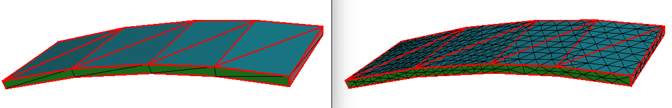
I have a very “simple” mesh that is slightly curved.
The initial geometry is parametric, and then tessellated.
Now what I want is to have MMGS refine this tessellated mesh, but without touching any “boundary” edge, so that the refined mesh fits exactly into the initial one.
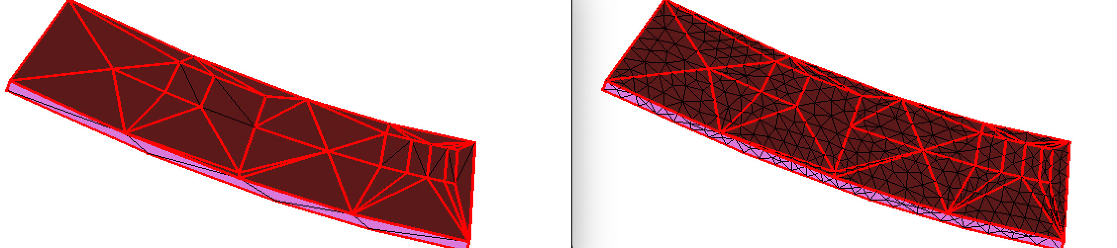
Here is the result :

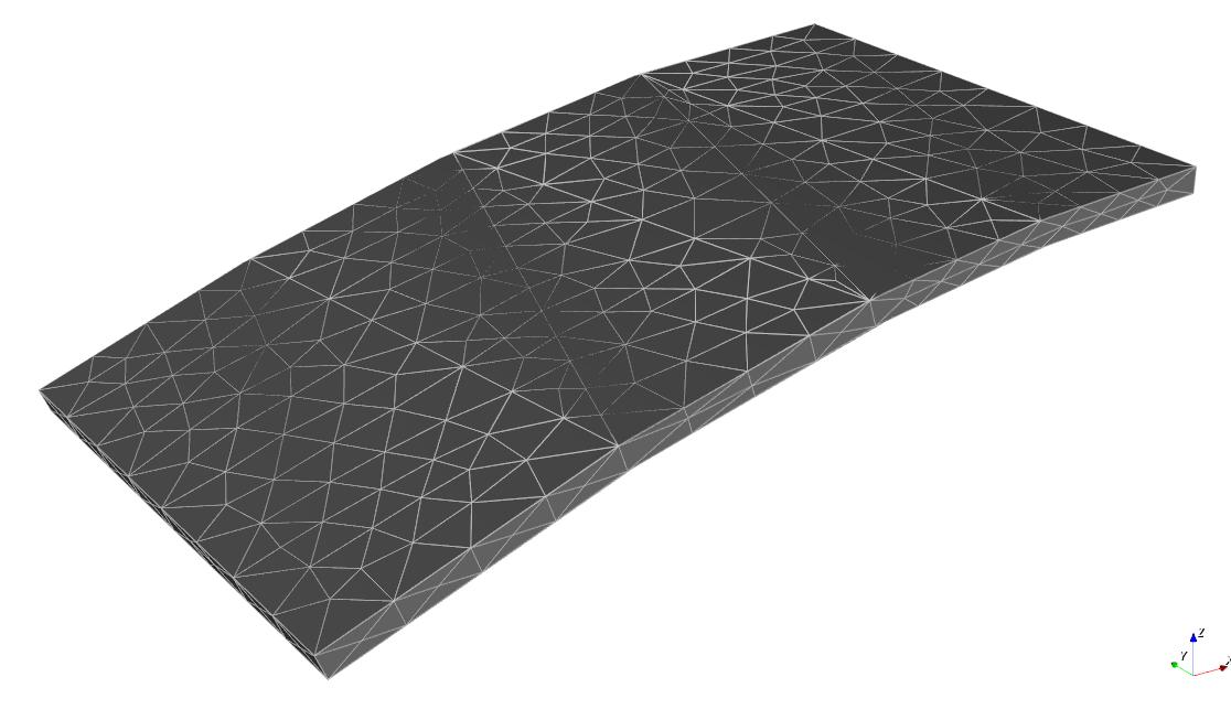
The Gray solid is the initial mesh.
The Silver wireframe is the result mesh.
You can see there are some places were the wireframe is swallowed by the initial mesh.

Closer look :


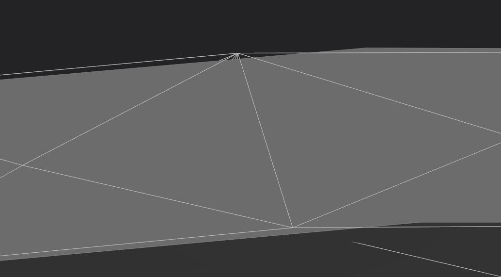
We can see that the result (wireframe) mesh is not fitting into the initial one, because MMGS has moved some edges/vertices.

What I’ve tried :

  • Setting AR to a very very small value (1E-5) to enforce each edge to be sharp.
  • Setting all boundary edges as Ridges
  • Setting all boundary edges as RequiredEdges
  • Setting all boundary vertices as RequiredVertices

No matter what, the result is always the same (as far as sharp edges are concerned), and the result mesh is not fitting the initial on.

Could you give me some help on that one please ?
Tks very much !

Hi there,
Perhaps not all that helpful, but: This sounds rather similar to the problem I had when I was trying to stitch a set of meshes (Merging similar surfaces). In my case what was required was to set the RequiredEdges property to the edges that needed to be preserved. I will say that it took some help from @Algiane to get the formatting right. Maybe that is the case for you as well.
Sorry I couldn’t be of more help though.

Thanks for your help :slight_smile:
Yes I have already tried with “RequiredEdges”, formatting is good (I’m using MEDIT file as input) and I can see change in the output, but the required edges are not preserved.

My guess is that in my case, required edges are ridges between surface that are almost parallel, and this cause MMG to make some adjustments.

Hi,

Some feedback on your attempts (In the following, I use the term geometric boundary edges to designate the edges that define the geometry and to avoid that someone who would only read this post would understand the term boundary edges to mean all the edges of the mesh):

  • the small ar value should allow to adapt your mesh without curve boundary approximation and the ridges should not be moved along the surface. I am not sure why it doesn’t work: maybe it can be due to some precision issue? What is the distance between the input ridges and the output ones?
  • setting geometric boundary edges ar ridges should work too if there is no such an edge shared by 2 triangles belonging to the same plane;
  • Mmg should not remesh required edges but it doesn’t guaranty that Mmg will not try to build some smooth approximation on both sides of such edges: we can imagine some non geometric edge that connects one node (n1) along a required edge and one node (n2) along a non-required and non-ridge boundary edge. A bezier patch will be built using geometric info stored at n2 and the boundary approximation will not be smooth anymore.
  • Setting feometric vertices as required avoid the deletion of these vertices but Mmg can insert new nodes, swap edges etc. Moreover you will face the same issue of curve reconstruction than with required edges.

If you can share your mesh, it will be probably easier for me to guess what happens.

Best,
Algiane

Sure, here it is.
input.mesh (3.0 KB)

I’m also using a SOL file, but I don’t think issue has anything to do with it.
input.sol (178 Bytes)

Same input, but with Ridges (tessellation is not the same)
input + edges.mesh (3.3 KB)

Thanks for these inputs,

Using the first one (without input ridges) and running with an angle detection threshold of 1e-5 (-ar), I am not able to reproduce your issue (I have used a hmax value of 1 to force node insertion).
I attach the result of the Mmg analysis that shows the added ridges (-noinsert -noswap -nomove -ar 1e-5) as well as the mesh produced by mesh adaptation (`-ar 1e-5 -hmax 1).


As Mmg adds a required tag to nodes at the intersection of more than 2 “featured” edges, all the input nodes of the mesh are preserved and they keep the same coordinates (I have fast checked this with Medit so at 1e-6 precision).

I attach the final mesh so you can check if you detect some shift from the input geometry.
input.o.mesh (102.2 KB)

Note that I have used the commit b29c88dc (last commit of master branch).

For the second mesh that you sent, as only edges at angles near Pi/2 are marked as ridges, I am not surprise that Mmg built a smooth surface model.

Best,
Algiane

Thank you very much Algiane for your very interesting reply.
I’ll give a try to your settings.

Thanks Algiane for you kind answer … I’ve found the problem.
This is a bad mistake from my behalf :cold_sweat:
The model I was giving to MMG was not exactly the same as the one I was using for display, hence the visual edge shift.

AR 1e-5 does the job !
Sorry guy.

Thanks for the feedback and thanks for your help @ebknudsen .
I close the ticket!

Have a nice day.