Let the library user provide a callback function which will compute the scalarSol for level set remeshing

If I’m not mistaken, the scalar function whose level sets are computed by the function

  int  MMG3D_mmg3dls(MMG5_pMesh mesh, MMG5_pSol sol, MMG5_pSol met );

can only be specified in advance at the mesh vertices using the function

  int  MMG3D_Set_scalarSol(MMG5_pSol met, double s,int pos);

It think it would make a great new feature of MMG3D (and the other flavours as well) if one could instead provide a callback function that mmg will call wherever necessary — not just mesh vertices – to get the scalar level value. The proposed signature is

  int  MMG3D_mmg3dls(MMG5_pMesh mesh, double (*get_scalarSolp)(double, double, double), MMG5_pSol met );

– just the same as the original one, but the middle argument is a callback function that maps x, y, z to the level value.

Can mmg level-set multiple level functions at once? If yes, the middle argument would look a little more complicated. (If not, that would be another feature request?)

Would such a function MMG3D_mmg3dls be hard to implement, and would that implementation make it possible for the library user to provide just a bounding box mesh and the distance-to-surface function and let mmg3dls do all the geometry resolution on its own :slight_smile: ?
The actual question is if that functionality is actually somehow present in mmg already, or if it would require some fundamentally new meshing algorithm?

Hi @Mathias-Fuchs,

Mmg allows only on level-set function at a time so your prototype of callback function would be suitable.

On the other hand, given the way isovalue discretization is implemented in Mmg, I don’t think that providing a callback function will do anything more than providing the discretization of the level-set function at nodes (without reimplementing lot of things). In the following, I suppose that you want to discretize the 0 value of the level-set. For now:

  1. we travel edges to detect those ones with vertices of different sign and to know which ones would be splitted. It means that an edge, either is not splitted by the level-set function, or is splitted exaclty one time;
  2. we create the new nodes by linear interpolation;
  3. we split the tetrahedra.

During all the process, the level-set values may be slightly modified to ensure:

  • that we don’t create too bad quality tetrahedra;
  • that the discretized surface will be manifold;
  • depending on the provided options, that we don’t create volumes that are too small or not connected to a boundary condition;

If we suppose that the user can provide the definition of the level-set, the function can be anything, so:

  • In the first stage, either we treat the continuous function as the discrete one (i.e. we check the values at vertices and allow to split edges only once) and, in this case, to provide the discrete or continuous function will make no difference, or we want to treat the case where the continuous function changes sign more than once along the edge. This last case is complicated because it asks, first, to be able to detect efficiently the splitted edges (an edge with two vertices with same sign may now be splitted an even number of times), and to implement lot of new patterns for element splitting. Indeed, I think that it is almost impossible to manage this in a robust way (for me the topological consistency would be really hard to ensure because, at a given point, computation still remains in a discrete world and the function can’t be continuously representated so we will have to check the manifoldness and the physical sense of the discrete surface found… but it will be a lot harder).
  • the second stage can take advantage of the continuous definition of the function for the computation of the position of the new nodes along edges. Though, I don’t know if it’s necessary to be so precise because in multiple locations, the level-set is modified to ensure a suitable topology and a good mesh quality. Moreover, after the level-set insertion the surface remeshing uses an approximation of the surface representation. I also wonder if a more precise cutting can create oscillations in the surface model (we have experienced such kind of issues with quadratic cutting): the surface elements will have a worse quality which may impact the boundary approximation. It is an opened question…
  • the third stage is independant from the level-set definition (if we suppose that an edge can be splitted only once);

As a conclusion, If your input bounding box mesh has a resolution linked to your implicit function you will not have different results with Mmg if you provide the definition of the level-set function than if you provide its discretization at nodes. If you want to provide an input mesh whose resolution is not linked to your implicit function, you will not be able to manage it with Mmg (and I don’t think that you will find a software able to produce simulation meshes in a robust way).

Sorry for the long answer but it was an interesting question that required some thought ;-).

Best Regards,
Algiane

Thanks a lot for the detailed answer, @Algiane.
I’m only thinking of the case where the surface is represented in a CAD program – for instance as a NURBS surface or whatever – , and the level function is its signed distance function. This is the approach you suggested here , if I understand correctly. In that case, if two vertices v, w are at distance || v-w || apart from each other, the level function f can only vary by the amount |f(v) - f(w)| \le ||v - w || by the triangle inequality (it is Lipschitz-continuous with Lipschitz constant 1). So, if |f(v)| > || v-w || or |f(w)| > || v - w || then f can’t be zero on the interior of the edge. So, in that case, mmg would not have to bother with querying the level function on the interior of the edge, or subdividing that edge.

In any case, I see there are good reasons why the level function should only be given at the vertices, I’m totally fine with that.

On the practical side, here is a simple example C program. Let’s take the unit ball to serve as an example of a solid given in a CAD program. It more-or-less works acceptably - iterative refinement where in each iteration, the distance to the surface is evaluated at the vertices, and then mmg is asked to refine it according to the distance function. The only problem is that there are small areas where the number of vertices explodes, disregarding the hmin setting. Unfortunately this explosion of vertices makes the result very hard to use for FEM - some tetrahedra have a very bad quality. See the screenshot below. Is that related to the oscillation problem you mention? It would be extremely cool if you had an idea how to improve the program, or point me to the place in the mmg source code where those excessive divisions occur.

If this level set approach is unusual, what is the recommended approach to generate a tet mesh of the interior of a solid given in CAD? Let’s assume I want to stick to mmg, not use other meshers. The following already works quite ok.

#include <mmg/mmg3d/libmmg3d.h>
#include <math.h>
int main() {
    MMG5_pMesh mmg3dMesh=NULL;
    MMG5_pSol mmg3dSol=NULL;
    MMG3D_Init_mesh(MMG5_ARG_start, MMG5_ARG_ppMesh, &mmg3dMesh, MMG5_ARG_ppMet, &mmg3dSol, MMG5_ARG_end);
    MMG3D_Set_meshSize(mmg3dMesh, 8, 6, 0, 0, 0, 0);
    // the corners of the unit cube
    MMG3D_Set_vertices(mmg3dMesh, (double[]) {0,0,0,1,0,0,1,1,0,0,1,0,0,0,1,1,0,1,1,1,1,0,1,1}, NULL);
    // a tet mesh of the unit cube
    MMG3D_Set_tetrahedra(mmg3dMesh, (int[]) {3,6,7,8,2,5,6,8,1,2,4,5,2,4,5,8,2,3,6,8,2,3,4,8}, NULL);
    // refine this tet mesh to have max edge length 0.5 to split all edges
    MMG3D_Set_dparameter(mmg3dMesh, mmg3dSol, MMG3D_DPARAM_hmax, 0.5);
    MMG3D_mmg3dlib(mmg3dMesh, mmg3dSol);
    // let's now run an iterative procedure ten times to refine the mesh
    for (int j=0;j<10;j++) {
	int np;
	MMG3D_Get_meshSize(mmg3dMesh, &np, NULL, NULL, NULL, NULL, NULL);
	MMG3D_Set_solSize(mmg3dMesh, mmg3dSol, MMG5_Vertex, np, MMG5_Scalar);
	for (int i = 1; i < np+1; i++) {
	    double x,y,z;
	    MMG3D_Get_vertex(mmg3dMesh, &x, &y, &z, NULL, NULL, NULL);
	    // signed distance to the unit sphere inside the cube
	    MMG3D_Set_scalarSol(mmg3dSol, sqrt(pow(x-0.5,2)+pow(y-0.5,2)+pow(z-0.5,2))-0.5, i);
	}
	MMG3D_Set_dparameter(mmg3dMesh, mmg3dSol, MMG3D_DPARAM_ls, 0);
	MMG3D_Set_dparameter(mmg3dMesh, mmg3dSol, MMG3D_DPARAM_hmin, 0.05);
	MMG3D_Set_dparameter(mmg3dMesh, mmg3dSol, MMG3D_DPARAM_hmax, 0.1);
	MMG3D_mmg3dls(mmg3dMesh, mmg3dSol, NULL);
    }
    MMG3D_saveMesh(mmg3dMesh, "x.meshb");
    MMG3D_Free_all(MMG5_ARG_start, MMG5_ARG_ppMesh, &mmg3dMesh, MMG5_ARG_ppMet, &mmg3dSol, MMG5_ARG_end);
    return 0;
}


(In reality, the problem is similar but worse - there are different materials in the model, each material being a solid. I have to run this iterative procedure for each solid so that in the end each tetrahedron is inside one and only one solid. Vertices on the surface of one solid should not be destroyed by level-setting the distances to the other solids, so they have to be set “required”).

Don’t get me wrong, mmg is really doing an amazing job here. Maybe the “local explosion problem” can be solved with some Gaussian or Laplacian smoothing?!

Thanks!

Hi @Mathias-Fuchs,

1. CAD surface

Thank you for the mathematical explanation. I guess that the Lipschitz-continuity is a property of the signed distance function?
Even if mainly developped for the discretization of a level-set of signed distance function, the ls option of Mmg can be used on other kind of discrete data (bathymetry for example).
In a totally non-mathematical point of vue, the issue I was afraid to face with a continuous function is the one described in the attached picture (it is direcly linked to the transition from the continuous to the discrete domain): with discrete data, it is clear that we will not know that the red edge has to be splitted, with continous data, the user can expect Mmg to split twice the edge…
dessin
But maybe such a function definition doesn’t make sense?

2. Local explosion problem

The issue you have is that Mmg adds feature edges (non-manifold ridges) at the intersection of the discretized level-set and the bounding box. Once added, Mmg keeps these edges and accumulates them as the level-set evolves.

I have modified your program with a temporary solution:

  • at the beginning of each iteration of the loop, the mesh is entierly reinitialized : memory is freed and reallocated and the input mesh is readed in a file;
  • the explicit setting of “iso” (for isosurface) mode using the MMG3D_IPARAM_iso variable is needed because it says to the MMG3D_loadMesh function to delete the previously discretized isovalue (that is, the two domains, the triangles and the feature edges belonging to the isosurface);
  • at the end of the iteration, the new mesh with discretized isovalue is saved.

prog.c (2.8 KB)

I know that it is not perfect because it adds I/Os: I will try to isolate the level-set cleaning (done only when parsing a mesh file for now) and to add a call to this cleaning to the MMG3D_mmg3dls function as soon as possible (it should be transparent from the user point of vue).
Maybe the adding of some API functions to manually delete edges from the mesh can be useful.
Do not hesitate if you have another suggestion.

Best regards,
Algiane

Thanks for the answer, @Algiane !

  • as for the feature suggestion of a callback function: maybe the users would have to submit a Lipschitz constant K together with their level function f such that they can promise that their level function satisfies
| f(v) - f(w) | \le K || v - w ||

for any two points v, w in their domain. For signed distance functions, they can set K=1, and for bathymetry data, K can be chosen as the maximum occurring steepness of the sea floor!
If the level set function is differentiable, they can choose K = max( || \nabla f ||) , the maximal steepness. I think it would be fair to ask that much “collaboration” from the user because a non-Lipschitz continuous level function would be really nasty anyway.
If mmg knows K, then it can decide whether there’s a chance f - f_0 has two or more zeros on the interior of an edge even though it doesn’t change sign on the edge’s vertices, as in your graphic. Here, f_o is the value of MMG3D_DPARAM_ls. So, it would have to subdivide the edge only if either |f(v)| or |f(w)| is less than K || v - w || and this should not occur very frequently. So, mmg could subdivide only the pathological edges as in the graphic, without having to query the level function excessively.
Ideally, this feature would allow to write the meshing strategy without a loop.

  • as for prog.c ok, thanks, I didn’t notice it’s the touching bounding box that introduces these extra edges.
    Do you suggest to retain only the vertices and tetrahedra between iterations, and discard all other data on required entities, ridges, etc? In that case, one might get rid of I/O relatively easily. One would just need to store vertices and tetrahedra, then free mmg3dMesh and mmg3dSol, and then populate it again with vertices and tetrahedra.
  • is there a particular reason to turn off angle detection?
    Maybe I should try to write a short example program that performs this level set tet meshing strategy on a more complex input surface. My actual application is in Rhino3D where it’s easier because one has the closest-point functions that allow to easily compute SDFs.
    Best, Mathias

Hi @Mathias,

I have turn off angle detection because the level-set function is smooth so normally we don’t want to detect sharp angles along the level-set.
But on your case (and I guess for a level-set that represents a CAD) there are no spurious edges added by the angle detection.

The issue when you disable angle detection is that you have to provide manually the ridges along the bounding-box. Thus :

  • if angle detection is enabled, you can retain only vertices and tetra between iterations. Aut as you have seen, you will have to free the mmg3dMesh because Mmg doesn’t provide API to remove edges (I will try to add this API because it can be useful indeed);
  • if angle detection is disabled, retaining only vertices and tetra between iterations will result in the loss of the input ridges that may be provided by the user. In practice, the user would like to recover its input edges but as Mmg has put ridges at the intersection of the level-set and the bounding-box, he will also recover the artifact ridges. Mmg has to be modified so that a user can iteratively call level-set discretization with the angle detection turned to off.

Best Regards,
Algiane

Thanks for the explanation.
Level set-functions might not always be smooth (infinitely differentiable). For instance, the “medial axis” which is used in shape recognition is the locus where the SDF is not differentiable, see for instance here. One can only safely assume it is continuous, or better and slightly stronger … Lipschitz-continuous (sorry to bother with that again.) I have no idea if you need continuity or smoothness for that sharp angle detection?
I guess, for now, in light of the example code, the only feature that is needed to use mmg for meshing 3d solids defined by enclosing surface meshes is to clear a mesh and reset a mesh to the state as if it was saved to read in again from a .mesh file as you do in the script:

  • save it to file
  • free the data
  • init a new mesh
  • read the mesh back in.

Would that make sense?
Best regards,
Mathias

Hi @Mathias-Fuchs ,

Thanks for the explanation : I probably confused it with the levet-set of the signed distance function. I think that we need continuity for sharp angle detection. In practice we can always detect sharp angles along the level-set but smooth functions intrinsically must not have sharp angles so what we detect in this case are artifacts.

Your workflow description is correct!

Best

Ok, do you think it would be possible to add a function to the 3d API that has the same effect as these four steps, so that one doesn’t need I/O?
I think that would be at least as useful as a new function to delete edges.
If you give me a short high-level introduction into where to start (as in which source file) and what to do there, I can try to write that function myself and then do a PR.
If mmg has a lot of internal state, it would be very useful/necessary to have an API function to clear that state.

As for angle detection: Peyré talks about the SDF in his tweet. Whether signed or not signed makes no difference in the interior. The distance function is not smooth on the medial axis, only (Lipschitz-)continuous, and by consequence, the level sets are not always smooth curves either.
Only outside the medial axis they are usually smooth. So, do you suggest to turn angle detection off just for the sphere example, or for SDF level functions in general, despite of that? To be honest, I always thought “angle” referred to interior angles of output tetrahedra. I’m only now vaguely understanding that it refers to curving angles of the level set, somehow.

Hi Mathias,

Thanks for your very nice proposition of contribution but this workflow will only work in your specific case, where sharp angle detection can be enabled so it may be confusing for other people.
Moreover, I don’t think that it is clean to perform the cleaning of the previous level-set in the file parser (this treatment is coded there only because Mmg was originally developed as a stand-alone application).

I understand that passing through I/Os is annoying : what delay would be accetable to you for me to correct the problem?

Beside, thanks for the mathematical explanations!

The angle detection option in Mmg computes the angle between boundary triangles (even if triangles are not provided by the user or if they are at the interface between 2 domains as for the level-set case). Then it creates ridges if the edge at triangles interface creates a sharp angle (edge along which the surface is C0).
This option adds the sharp angle markers for the 12 eges of an input cube for example.

The level-set discretization option of Mmg was initially coded to shape optimization problems. In this case, the implicit surface defined by the level-set creates lot of spurious angles, so I am used to disable this option when discretizing level-sets (see the red lines on attached picture).

For your workflow, my opinion is that if you didn’t notice any troubles so far, don’t change anything to your code!

Best Regards,
Algiane

Hi Mathias,

I hope that you are well.
I have just pushed a proper version of the cleaning of the isosurface in the develop branch of Mmg. You will still have to copy your mesh and to free and realloc the Mmg data structures between 2 iterations but now it is not anymore mandatory to pass through I/Os in order to remove the previous isosurface.
Do not hesitate to test and to contact me if it doesn’t work.

Best Regards,
Algiane

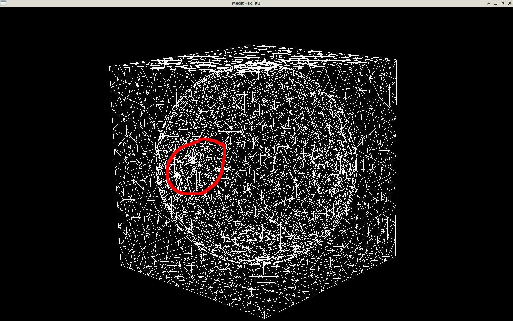
Thanks, @Algiane . Yep, I’m fine. Without I/O it is much more usable now and the sphere mesh generated by the program now looks good! Ok, I see what angle detection does. It seems I can’t turn it off because the edges of the input cube are necessary. So, is the following program what you recommend to do at the end? I rewrote your program but turned angle detection on, and removed I/O, instead just memorizing vertices and tetrahedra in a buffer between iterations.

#include <mmg/mmg3d/libmmg3d.h>
#include <math.h>
#include <stdio.h>
#include <stdlib.h> // for malloc

int main() {
	MMG5_pMesh mmg3dMesh = NULL;
	MMG5_pSol mmg3dSol = NULL;
	MMG3D_Init_mesh(MMG5_ARG_start, MMG5_ARG_ppMesh, &mmg3dMesh, MMG5_ARG_ppMet, &mmg3dSol, MMG5_ARG_end);
	MMG3D_Set_meshSize(mmg3dMesh, 8, 6, 0, 0, 0, 0);
	// the corners of the unit cube
	MMG3D_Set_vertices(mmg3dMesh, (double[]) { 0, 0, 0, 1, 0, 0, 1, 1, 0, 0, 1, 0, 0, 0, 1, 1, 0, 1, 1, 1, 1, 0, 1, 1 }, NULL);
	// a tet mesh of the unit cube
	MMG3D_Set_tetrahedra(mmg3dMesh, (int[]) { 3, 6, 7, 8, 2, 5, 6, 8, 1, 2, 4, 5, 2, 4, 5, 8, 2, 3, 6, 8, 2, 3, 4, 8 }, NULL);
	// refine this tet mesh to have max edge length 0.5 to split all edges
	MMG3D_Set_dparameter(mmg3dMesh, mmg3dSol, MMG3D_DPARAM_hmax, 0.5);
	MMG3D_mmg3dlib(mmg3dMesh, mmg3dSol);

	// let's now run an iterative procedure ten times to refine the mesh
	for (int j = 0; j < 10; j++) {
		int np, ne;
		MMG3D_Get_meshSize(mmg3dMesh, &np, &ne, NULL, NULL, NULL, NULL);
		double* verts = malloc(3 * np * sizeof(double));
		int* elements = malloc(4 * ne * sizeof(int));
		MMG3D_Get_vertices(mmg3dMesh, verts, NULL, NULL, NULL);
		MMG3D_Get_tetrahedra(mmg3dMesh, elements, NULL, NULL);

		// Free mesh and reopen it to have a clean analysis
		// As we want to discretize a new isovalue,  cleans all info related to previous isovalue:
		//  - interior and exterior domains;
		//  - triangles on the isosurface;
		//  - ridge and non-manifold tags added to edges at interface of the bounding box and previous isosurface.
		// by freeing everything and reading the vertices back in.
		MMG3D_Free_all(MMG5_ARG_start, MMG5_ARG_ppMesh, &mmg3dMesh, MMG5_ARG_ppMet, &mmg3dSol, MMG5_ARG_end);
		MMG3D_Init_mesh(MMG5_ARG_start, MMG5_ARG_ppMesh, &mmg3dMesh, MMG5_ARG_ppMet, &mmg3dSol, MMG5_ARG_end);
		MMG3D_Set_meshSize(mmg3dMesh, np, ne, 0, 0, 0, 0);
		MMG3D_Set_vertices(mmg3dMesh, verts, NULL);
		MMG3D_Set_tetrahedra(mmg3dMesh, elements, NULL);
		MMG3D_Set_solSize(mmg3dMesh, mmg3dSol, MMG5_Vertex, np, MMG5_Scalar);
		for (int i = 1; i < np + 1; i++) {
			double x, y, z;
			MMG3D_Get_vertex(mmg3dMesh, &x, &y, &z, NULL, NULL, NULL);
			// signed distance to the unit sphere inside the cube
			MMG3D_Set_scalarSol(mmg3dSol, sqrt(pow(x - 0.5, 2) + pow(y - 0.5, 2) + pow(z - 0.5, 2)) - 0.5, i);
		}

		// Specify to Mmg that we want to discretize a new isovalue
		MMG3D_Set_iparameter(mmg3dMesh, mmg3dSol, MMG3D_IPARAM_iso, 1);
		MMG3D_Set_iparameter(mmg3dMesh, mmg3dSol, MMG3D_IPARAM_verbose, 5);
		// turn angle detection on
		MMG3D_Set_iparameter(mmg3dMesh, mmg3dSol, MMG3D_IPARAM_angle, 1);
		MMG3D_Set_dparameter(mmg3dMesh, mmg3dSol, MMG3D_DPARAM_ls, 0);
		MMG3D_Set_dparameter(mmg3dMesh, mmg3dSol, MMG3D_DPARAM_hmin, 0.05);
		MMG3D_Set_dparameter(mmg3dMesh, mmg3dSol, MMG3D_DPARAM_hmax, 0.1);

		MMG3D_mmg3dls(mmg3dMesh, mmg3dSol, NULL);
		free(verts);
		free(elements);
	}

	MMG3D_saveMesh(mmg3dMesh, "x.meshb");
	MMG3D_Free_all(MMG5_ARG_start, MMG5_ARG_ppMesh, &mmg3dMesh, MMG5_ARG_ppMet, &mmg3dSol, MMG5_ARG_end);
	return 0;
}

We might be nearing the solution to the old problem Can mmg3d be used to turn an unconstrained to a constrained Delaunay tetrahedralization? .
However, I really wonder why what we’re doing is so complicated. It’s all about having mmg respect boundaries between materials … say, plastic and steel for a heat conduction problem. Respecting material boundaries should be a very common task in tetrahedral meshing. That was and is the motivation for all my questions.
Cheers, Mathias

(By the way, I’m not using cmake but instead I link dynamically and specify the location of include folder, and mmg.lib and mmg.dll explicitly in Visual Studio because my main project simply doesn’t use cmake. Recently, I had to include not only the folder

[installation directory]\include;

but also the folder

[installation directory]\include\mmg;

It seems this is not quite the intended behaviour, is it? All of this is a little complicated because the mmg source files include files that do not exist in the source tree, only in cmake’s copy of it inside the build directory.)

Hi @Mathias-Fuchs ,

Your program looks good: if the results are what you expect, then this is the one I recommend ;-).

For your question about constrained Delaunay tetrahedralization, the difficulty of this task entirely hold in the boundary recovery (that is, the fact that you want to recover the input surface triangulation when generating your volume mesh). Even if the problem as been solved since few decades, it asks for a robust impliementation that can take time (https://albertsk.files.wordpress.com/2011/12/si-atms-2015-10-1145_2629697.pdf). In our case, as Mmg is a research software, dedicated to remeshing and not mesh generation, and as robust constrained Delaunay tetrahedralization has already been implemented in other open source software (Tetgen for example), the implementation of such a tool is not a priority.

Thanks for your feedback on the issue with include directories: I will try to solve it before the next release.

Best Regards,
Algiane

Why is respecting boundaries only a mesh generation problem, not a remeshing problem?
Each tetrahedron in a mesh must be entirely within one material, not cut through material boundaries, and this property must be preserved during remeshing. I thought that’s what the “references” in mmg are for.
Asking for respecting material boundaries is weaker than full boundary recovery aka constrained Delaunay.
I know tetgen and have used it a lot but it is unsuitable for writing a Rhino3D plugin due to its restrictive license.
Cheers, M

Hi,

It is just a different issue for meshers that remesher:

  • the work for the remeshers is pretty simple: they have to forbid remeshing operators along the input surface. The only concern being: is the remesher able to reach sufficient qualities near freezed entities?

  • the work for meshers is a lot harder. To my knowledge (note that I am not an expert in mesh generation algos :wink: 
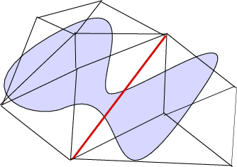
), the algorithm to generate the interior mesh of an input triangulation is the following:

    • creation of a bounding box that contains the input triangulation;
    • volume mesh of this bounding box;
    • insertion of the nodes of the input triangulation inside the volume mesh. At the end of this step, the mesh contains all the nodes of the input triangulation but some edges and triangles of this surface are missing (for a 2D illustration see for example the illustration of the mesh generation of the CDT word here: Constrained Delaunay, some edges of the letter D are missing in the upper mesh). This is why we need the next step.
    • boundary recovering: missing edges and triangles have to be recovered: this step is pretty simple in 2D. Missing input boundary edges can be recoverd by random flips of mesh edges that intersect them. But in 3D it is tricky: it is not always possible to recover the input triangulation without inserting temporary additionnal nodes (the Steiner points) and identifying wether it is possible or the number of needed Steiner points is very hard.
    • coloration of the mesh inside the input triangulation;
    • deletion of the external part (bounding box deletion).

The step of boundary recovering it those one that is missing to directly use Mmg as mesh generator. Unfortunately, it is not a small implementation step…

Best Regards,
Algiane

I see, thanks for the explanation.
But do people really expect to recover all triangles of their surface mesh?
Maybe they are happy to have a tetrahedral mesh that respects the volume of their geometry and all material boundaries (doesn’t “cut through” material boundaries).
If that is the case, our little program’s strategy (successively remesh the signed distance function) basically achieves that, doesn’t it?
I think it turns, for most practical intents and purposes, mmg from a remesher into a mesher :slightly_smiling_face:

Hi,

The needs of recovering the triangles of the surface mesh depends on the application and the method of acquisition of the boundary mesh.

This said, even if the user accepts the modification of the surface mesh, it is needed to recover the boundary mesh before starting volume mesh modifications to avoid the creation of errors in the boundary approximation. Authorizing surface modification releases some constraints of course but due to the fact that it is hard to predict areas where boundary recovering is tricky, this remains a difficult problem.

But I agree that from an engineering point of vue it would be a useful option (if only we had the possibility to have more developers !)

Best Regards,
A.