Can mmg3d be used to turn an unconstrained to a constrained Delaunay tetrahedralization?

Hello,
… back working with mmg after some while :slight_smile:
I’m trying to solve a similar situation as the one described in this recent thread: to go from a surface mesh to a tetrahedral mesh.
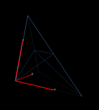
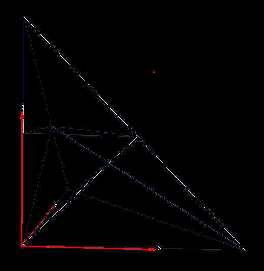
Starting from a set of points with triangles, in other words from a surface mesh, I would like to generate a tetrahedral mesh such that those triangles occur as faces of some of the generated tetrahedra.
The strategy is to:

  1. generate the Delaunay tetrahedralization of the points, because that seems to be the simplest way to draw sort-of well-behaved tetrahedra between the points. The union of the all these tetrahedra is equal to the convex hull of all input points. Moreover, good implementations of the Delaunay tetrahedralization can be found on the web. We don’t need to use mmg3d for this step.

  2. use mmg3d to require the given triangles from the surface mesh. This step should amount to turning the unconstrained Delaunay tetrahedralization into a constrained Delaunay tetrahedralization. Since the triangles cut the tetrahedra in potentially awful ways, this step amounts to asking mmg3d to do a lot of remesing of all those tetrahedra that intersect one of the triangles.

  3. remove the tetrahedra outside the triangles, assuming that the initial surface mesh was a solid in the sense that it was connected, had no non-manifold edges, and no naked edges. This step is done with the help of some BSP-tree or some similar technology.

Question: is part 2 an appropriate usage of mmg3d’s “require triangle” functionality?
Is the strategy described here a proper way to use mmg3d?
Are there input flags that should be used in this particular situation?
I understand that in order to preserve triangles that are not yet faces of tetrahedra, one has to use the opnbdy flag because these triangles are not between two references of tetrahedra.
Even though I get from other answers that such a usage is not what “require triangle” is made for, maybe one can save the situation by applying a good subdivision strategy before step 2?
EDIT: it should be sufficient to assume that the constraints are planar. Maybe one can “manually” intersect all tetrahedra with the plane before applying mmg3d?
Actually, the intersection of a plane with a tetrahedron is either a tetrahedron and a prism, or two prisms (or degenerate and not important), and we can feed the prism or the two prisms into mmg3d.
Thanks, Mathias

Hi Mathias,

Glad to see you back!

From a general point of vue your proposition of algorithm makes sense but it will not be possible to use it with Mmg without an additional implementation step due to the way Mmg stores triangles: in Mmg3d, to avoid the update of multiple data structures when modifying the mesh, triangles and edges entities are stored within the tetrahedron to which they belong and deleted juste after the mesh input.
The mesh is then modified and we rebuild the boundary entities (triangle and edges) before giving back the mesh to the user.

Thus, if the input mesh contains triangles that are not faces of tetrahedra, those triangles are deleted (or more probably, Mmg returns an error message), even in opnbdy mode. The opnbdy mode is only useful to preserve triangles at interfaces of tetrahedra with the same reference but those triangles must match the tetra faces.

On the other hand, I think that you can implement the step 2 rather easily by using the isovalue discretization of Mmg (ls mode): if you can compute the signed distance of your surface mesh inside the tetrahedralization generated during the step 1, calling Mmg on the 0-level-set to discretize it should lead to generate the input triangulation (it will compute the intersection of the tetrahedron and the surface mesh) and the internal and external domains.

Then the step 3 can be done using the -nsd option that allows to choose the subdomain that should be keeped.

As you guess, you can also compute manually the intersection of the input triangles and the tetrahedralization, it will ask to split the tetrahedron following various patterns that are the same that those one used for the isovalue discretization (mmg3d2.c file, line 1193). Unfortunately, you can’t provide directly prisms to Mmg and ask to split the prisms (all the needed tools are implemented but not coupled together and not exposed to the user).

I hope that it will help you,
Best Regards,

Algiane

That’s a great idea, thanks, @Algiane !!
Tot try it out, here’s an example program with just one tetrahedron with vertices at (0,0,0) and the three unit coordinate vectors, and let’s try to enforce triangles along the constraint plane z = 1/2. Also thanks for the other hints.

#include <mmg/mmg3d/libmmg3d.h>
int main() {
	MMG5_pMesh mmg3dMesh = NULL;
	MMG5_pSol mmg3dSol = NULL;
	MMG3D_Init_mesh(MMG5_ARG_start, MMG5_ARG_ppMesh, &mmg3dMesh, MMG5_ARG_ppMet, &mmg3dSol, MMG5_ARG_end);

	MMG3D_Set_meshSize(mmg3dMesh, 4, 1, 0, 0, 0, 0, 0);
	MMG3D_Set_solSize(mmg3dMesh, mmg3dSol, MMG5_Vertex, 4, MMG5_Scalar);

	MMG3D_Set_vertex(mmg3dMesh, 0, 0, 0, 0, 1);
	MMG3D_Set_vertex(mmg3dMesh, 1, 0, 0, 0, 2);
	MMG3D_Set_vertex(mmg3dMesh, 0, 1, 0, 0, 3);
	MMG3D_Set_vertex(mmg3dMesh, 0, 0, 1, 0, 4);

	MMG3D_Set_tetrahedron(mmg3dMesh, 1, 2, 3, 4, 0, 1);

// signed distances of the four vertices to the plane z = 1/2
	MMG3D_Set_scalarSol(mmg3dSol, -0.5, 1);
	MMG3D_Set_scalarSol(mmg3dSol, -0.5, 2);
	MMG3D_Set_scalarSol(mmg3dSol, -0.5, 3);
	MMG3D_Set_scalarSol(mmg3dSol, 0.5, 4);

	MMG3D_Set_dparameter(mmg3dMesh, mmg3dSol, MMG3D_DPARAM_ls, 0);
	MMG3D_mmg3dls(mmg3dMesh, mmg3dSol, NULL);

	MMG3D_saveMesh(mmg3dMesh, "constrainedDelaunay3d.mesh");
	MMG3D_Free_all(MMG5_ARG_start, MMG5_ARG_ppMesh, &mmg3dMesh, MMG5_ARG_ppMet, &mmg3dSol, MMG5_ARG_end);
}

… it’s almost doing what we want, but not yet quite?! It splits the tetrahedron but not the way we hope grafik
Do we need to set another parameter (also MMG3D_IPARAM_iso or is that implied)? thx, M

Nice! you find a bug (due to an index error, the first edge to split in the mesh was never splitted). It is fixed in both the master and develop branch (65ba2da commit).

It should work now.

Looks great! I’ll try out to let mmg3d just save the subdomain on one side of the plane as you suggested. I see that mmg3d introduced tet references 2 for those above the plane and 3 below - I wonder where these numbers come from?
^

Hi,

It is an internal convention: the positive domain has ref 2 (MG_PLUS) and the negative domain ref 3 (MG_MINUS). I just move the definition from the common/mmgcommon.h file to the common/libmmgtypes.h one so it is visible for users now.

Have a nice week-end.