Hello,
I’m sorry to bother you.I have recently been trying to generate 3d anisotropic grids using MMG3D(Implemented by freefem + +),but it is found that the anisotropy of the generated grid is not strong,we want to generate grids that are more anisotropic, like a grid ratio of 1e6.May I ask if there is any way to solve this problem?Here is my program
load “msh3”
load “tetgen”
load “mshmet”
load "medit
load “mmg”
real epsilon=1e-6;
int b1=1;
int b2=2;
int b3=3;
func f=-y^2exp(b1(x-1)/epsilon)-xexp(b2(y-1)/epsilon)-zexp(b3(z-1)/epsilon)+exp((b1*(x-1)+b2*(y-1)+b3*(z-1))/epsilon)+xy^2z^3;
//func f=1/(1+exp((x+y+z-1)/(2*epsilon)));
int nn = 10;
int[int] lc=[1,2,2,1,1,2]; // label numbering
mesh3 Th=cube(nn,nn,nn,label=lc);
fespace Vh (Th,P1);
fespace Mh(Th,[P1,P1,P1,P1,P1,P1]);
Vh u=f;
Mh [m11,m21,m22,m31,m32,m33];
real lerr=0.05;
verbosity=3;
for(int i=0;i<8;i++)
{
[m11,m21,m22,m31,m32,m33]=[0,0,0,0,0,0];
real[int] met=mshmet(Th,u,hmin=1e-7,hmax=0.2,err=lerr,aniso=1);
m11[]=met;
Th=mmg3d(Th,metric=m11[],hgrad=100000);
lerr *= 0.5;
mesh3 Th1=trunc (Th,(x<0.5|y<0.5|z<0.5),label=1);
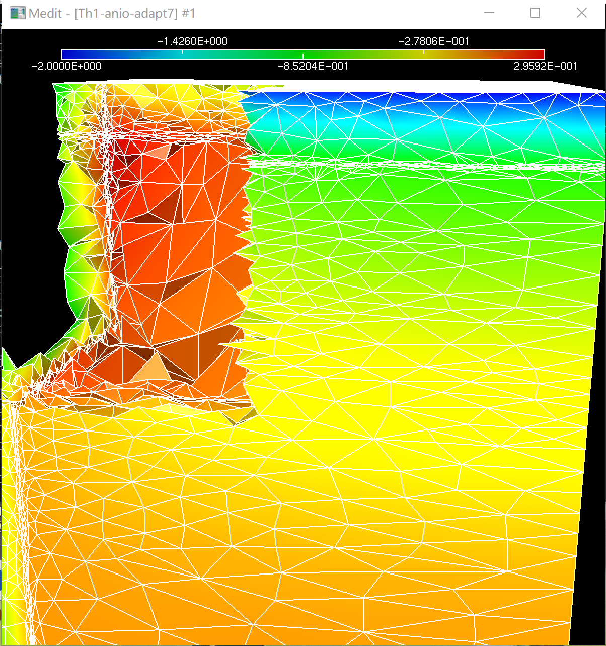
if(i>6) medit(“Th1-anio-adapt”+i,Th1,u,wait=1);
}
Thank you
Hi @xiaofei ,
Welcome to this forum.
Is it possible to save the mesh and metric at medit format just before the call to mmg3d and to attach them here (so I can try to look at what happens specifically on your test case)?
In general, the anisotropic ratio is truncated by the gradation (but gradation ensure to have a good quality mesh), but in your case, as you set the gradation to a very high value it should be something else…
Thank you by advance,
Algiane
Hi,Algiane,
Thank you for your answering. ‘mesh.mesh’ and ‘metric.txt’ are the mesh and the metric before using ‘mmg3d’.How could I adjust gradation to obtain a mesh which has larger anisotropic ratio?
Thank you !
mesh.mesh (152.0 KB)
metric.txt (111.2 KB)
Dear @xiaofei,
could you try in your FreeFem++ script to add
load "aniso"
real[int] met=mshmet(Th,u,hmin=1e-7,hmax=0.2,err=lerr,aniso=1);
boundaniso(6,met,40);
m11[]=met;
and tell me if now everything is OK ?
Sincerely,
GS
Hi,
Thanks for the files.
It seems that the metric you provide don’t contain high ratio of anisotropy.
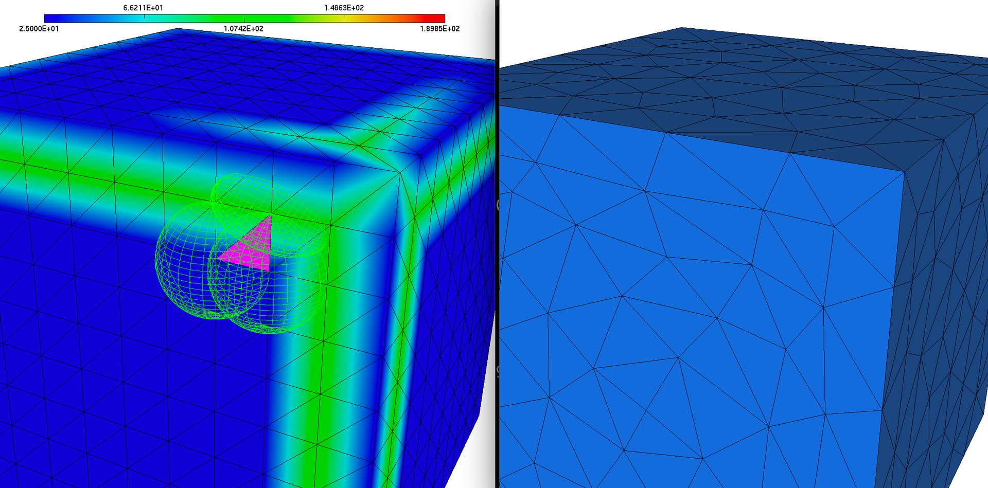
See the following image:
-
left is your input mesh and the provided metric with the anisotropic tensors provided at the 3 vertices of a given triangle. Ellipsoids represents the unit ball in the metric space and Mmg tries to create edges of lengths 1 in this space. From what I see,
hmaxis reached but we stay far fromhmin. Maybe thelerrparameter is too large ? -
right is the mesh created by Mmg (
masterbranch or last release) with gradation disabled (-hgrad -1). Sometimes it is also needed to disable the required gradation (that propagate sizes of required edges on neighbouring entities) using the-hgradreq -1option but it is useless in your case as you don’t have required entities. For me this mesh seems consistent with your inputs. Do not hesitate to tell me if you were expecting something different…
With the default gradation (1.3), the resulting mesh is weird and anisotropy is locally lost: the improvement of the gradation of Mmg is a work in progress and will be integrated in the annual release of Mmg (probably in november).
Please, let me know if @geosad proposition works (by the way: thanks  !).
!).
Have a nice evening.
A.
Hi @geosad
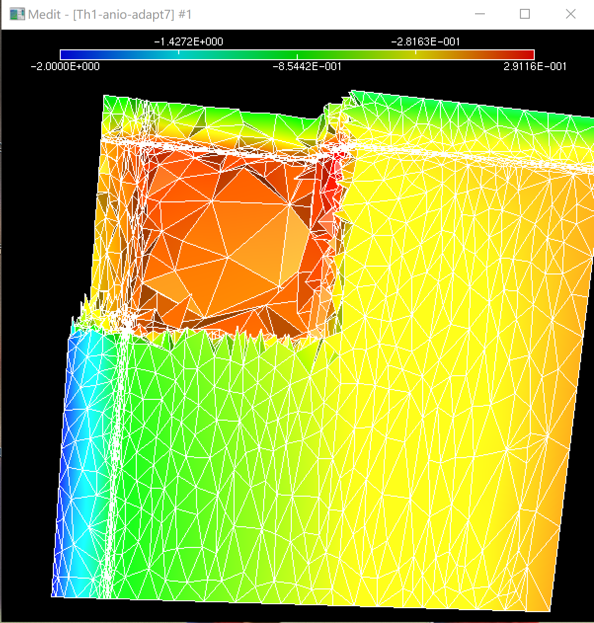
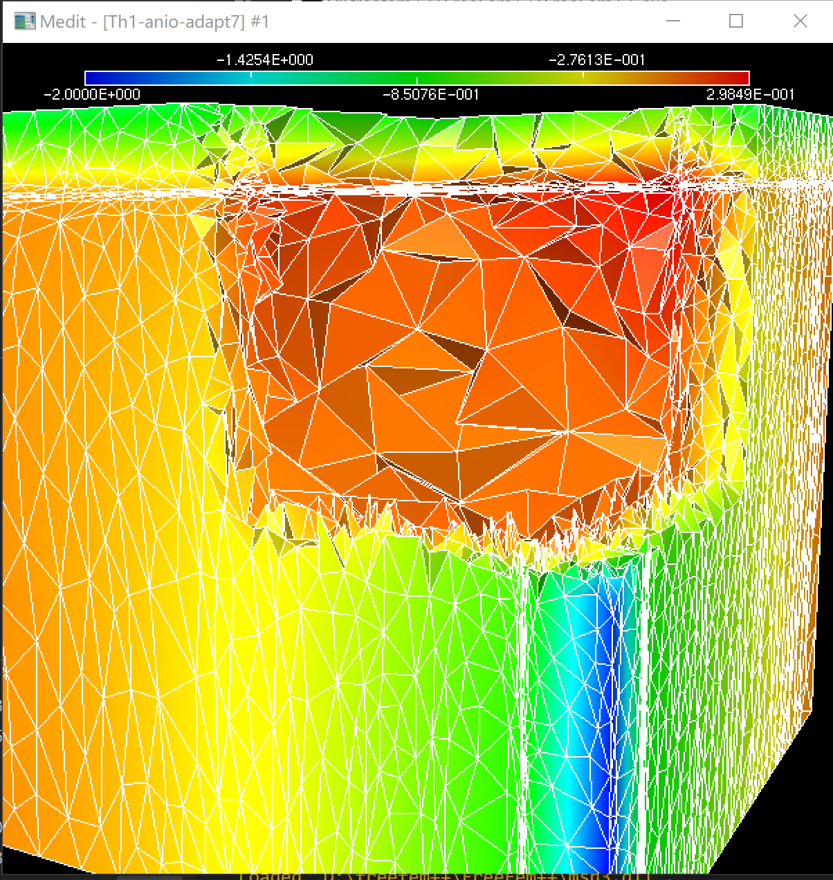
Thank you for your answer. I’ll add ‘load “aniso”’ and ‘boundaniso(6,met,40)’ to my program, The figure ‘left’ is the grid generated in your way,and the figure ‘right’ is the grid generated by my program. I looked in the FreeFem++ documentation and couldn’t find ‘boundaniso’ in detail. Could you tell me what the parameters of this command mean? In addition, which parameter in the output result of mmg3d represents the anisotropic ratio?
Thank you very much.
Hi Algiane,
Thank you for your reply. The file I sent before was the initial ‘mesh’ and ‘metric’, and then I added the cycle. As the cycle went on, the ‘mesh’ and ‘metric’ changed. Now I am sending you the ‘mesh’ and ‘metric’ after the cycle 8, please help me check it. I tried geosad’s method, and the ‘left’ is the grid generated by his method, the ‘right’ is the grid generated by my previous method.
Thank you very much.
mesh.mesh (3.8 MB)
metric.txt (677.8 KB)
Hi @xiaofei,
I am not sure to see the difference between the result with and without the boundaniso call. I guess that this function applies a truncation to the ration of anisotropy?
For the mesh and metric that you provide: do you think that there is an issue with the remeshing on this data? Finally, did you run with a disabled gradation (hgrad=-1)?
The metric.txt file that you provide seems truncated: your mesh contains 20400 vertices but the metric file is only 52758 lines (so values at 8794 vertices)…
Best regards,
A.
Dear @xiaofei and @Algiane
the boundaniso bounds the ratio of the eigenvalues of the metric.
if l1,l2,l3,l4,l5,l6 are the 3 eigenvalues then the 3 news eigenvalues are
boundaniso(6,met,40)
lx = max(l1,l2,l3,l4,l5,l6)
cc = 40
l1 = max(lxcc,l1);
l2 = max(lxcc,l2);
l3 = max(lxcc,l3);
l4 = max(lxcc,l4);
l5 = max(lxcc,l5);
l6 = max(lxcc,l6);
the optimal tetreatedre are such that the lengths of the edges in the metric are 1.
the value 6 in boundaniso(6,met,40) is for 6 eigenvalues of the metric.
Sincerely,
GS
cc = sqrt (40)
lxcc = lx * cc
Dear geosad
I see. Thank you very much for your answer.
Thank you.