hello,
I use mmg for working with FreeFEM++. I create the geometry in gmsh. While computing an integrated quantity in FreeFEM++ which involves element normals along a border, I found a mis-match. With the mesh from gmsh, I am getting (for. eg) 0.9 (which is expected), but on passing the mesh through mmg2d with -noinsert flag and computing I get (-0.9).
Hope you undertstand the concern. If I need to use some flags to resolve this, please let me know
Regards
Tom
Hello Tom,
Welcome to this forum.
Is it possible to attach the input mesh you give to mmg2d and its output mesh?
If I correctly understand your problem, after calling Mmg2d, the mesh edges are no longer oriented in accordance with the mesh triangles…
Thank you by advance,
Regards,
Algiane
Here you go. If you have FreeFEM you can easily debug this using a script in FreeFem++ i attach here.cylinder.msh (46.0 KB)
mcylinder.msh (59.8 KB)
cylinder.msh is from gmsh
mcylinder.msh from mmg: mmg2d_O3 in cylinder.msh -out mcylinder.msh -noinsert
label 5 one of the inner boundary label.
you can try 2,3,4,5,6. in the code and change (N.x<1e-10) to (N.x>1e-10) for more.
I think mmg is following a different convention than from FreeFEM++
Thanks for your reply
Regards
Tom
Hi Tom,
Thank you for this script (as I am a beginner in FreeFem++ it has been very useful).
I have pushed a patch to have the same orientation for all the edges of a boundary of a given pysical domain (develop branch of mmg2d).
Beside, you can still have issues:
- Mmg2d don’t store the boundary entities of a mesh, it keeps only the mesh elements;
- At the end of the remeshing process, we reconstruct the boundaries of the mesh from the elements;
- Thus, if a triangle doesn’t have a neighbour through an edge, we create an edge oriented with respect to the triangle;
- If a triangle has a neighbour with a different reference (=color) we must choose with which triangle we will orient the edge:
- previously, we were oriented the edge with the triangle of maximal index (so two edges of a domain may have a different orientation);
- now, we orient the edge with respect to the domain with maximal reference;
In your test case it works because the gmsh physical references allows to obtain the same edge orientation than Mmg but as I don’t know the Gmsh (or the FreeFem++) convention, it is possible that sometimes you will ended with flipped edges. In this case, the only solution is to use a different numbering of the domain to impose the wanted edge orientation to Mmg.
I hope that it will help,
Regards,
Algiane
Thank you. And, my pleasure as I have to make you understand the problem I was facing. I hope mmgs and mmg3d is clear of this bug, so that I can confidently use it ? (At present everything works fine as far as normal orientation is concerned.)
Thanks again,
Tom
Hi Tom,
In 3D the problem is slightly different:
-
For mmg3d (volume remesher), the interfaces between two different domains will be triangles. We take care of the triangles orientation. The orientation of edges is not implemented (and requires a little works). Please, can you confirm that it is not an issue?
-
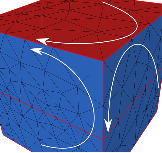
Mmgs can be used on 2D-like meshes so I have added the edge orientation as it is done for Mmg2d (develop branch, commit ae24dda): edges between domains with different references are oriented with respect to the triangles of the domain of higher reference.
But as mmgs deals with 3D surface meshes, we can have “geometric” edges (due to sharp angle detection for example) between triangles of same reference. In this case, we can not orient the edges because we don’t know which triangle must impose its orientation (see the attached picture for example, the white arrows give the edge orientation that is choosen. Between the red and blue faces, it is easy to impose an orientation, but not between the 2 blue faces).
Regards,
Algiane
Thanks ! For the same physics I am solving in 3D (the 3D code) doesn’t have that issue at present, thus I believe there is no problem. I will get back to you if I come across something.
Thanks again
Tom

