
Hello,
trying to build a meshing module based on the Opencascade geometry kernel and MMG.
In short summary:
it is possible to, and it works:
-
to read a .step file using the opencascade reader
-
retrieve shape triangulation (could be a single face, or a shell, or a solid, or a composite solid) which is used for visualization purposes
-
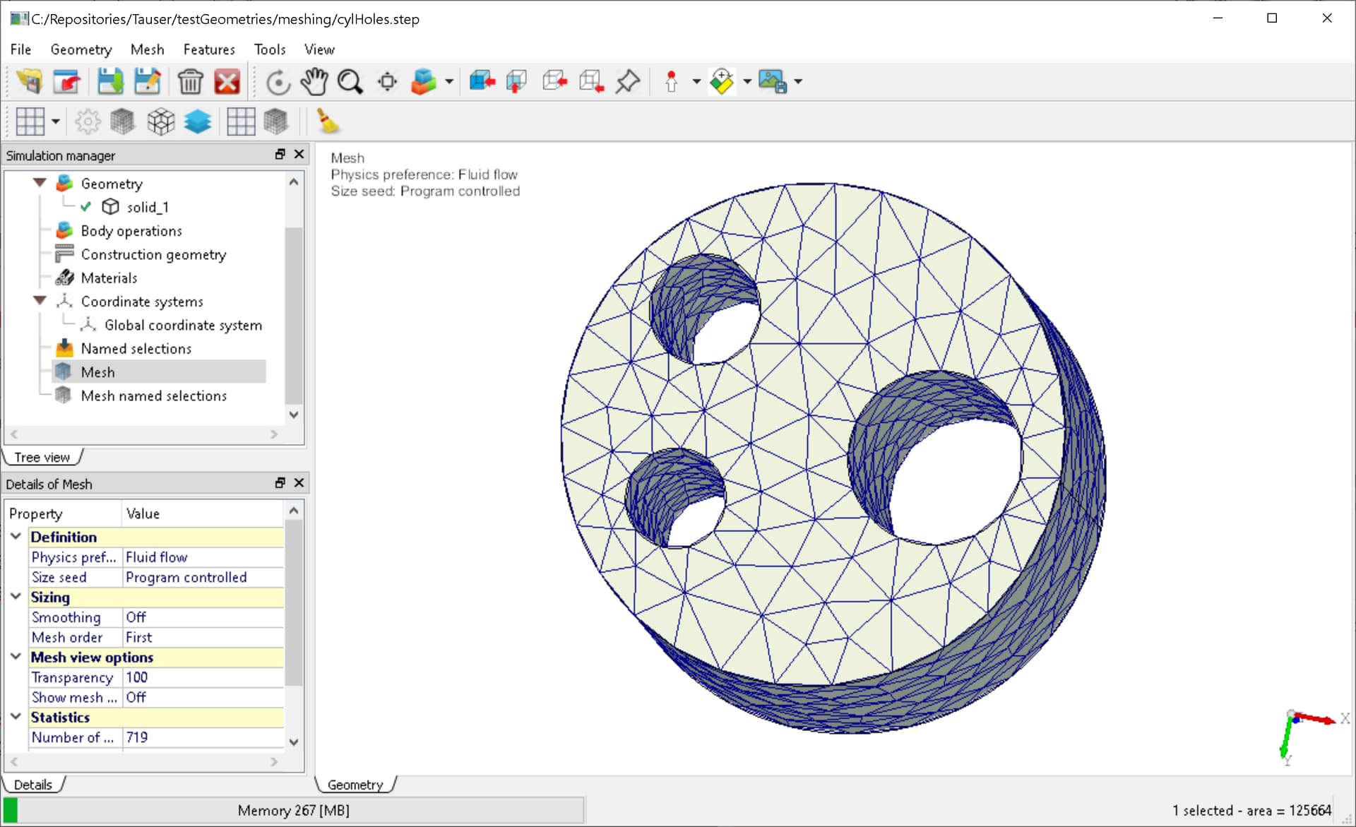
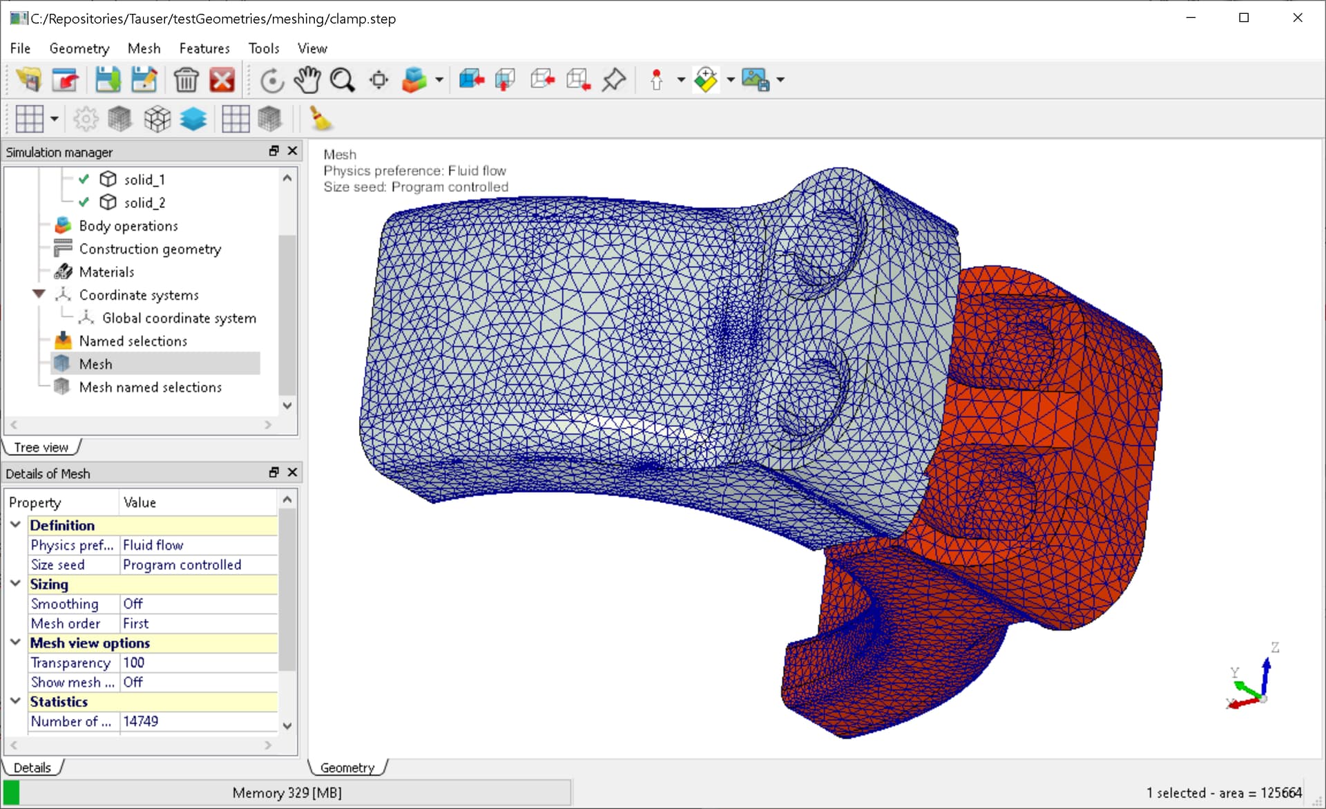
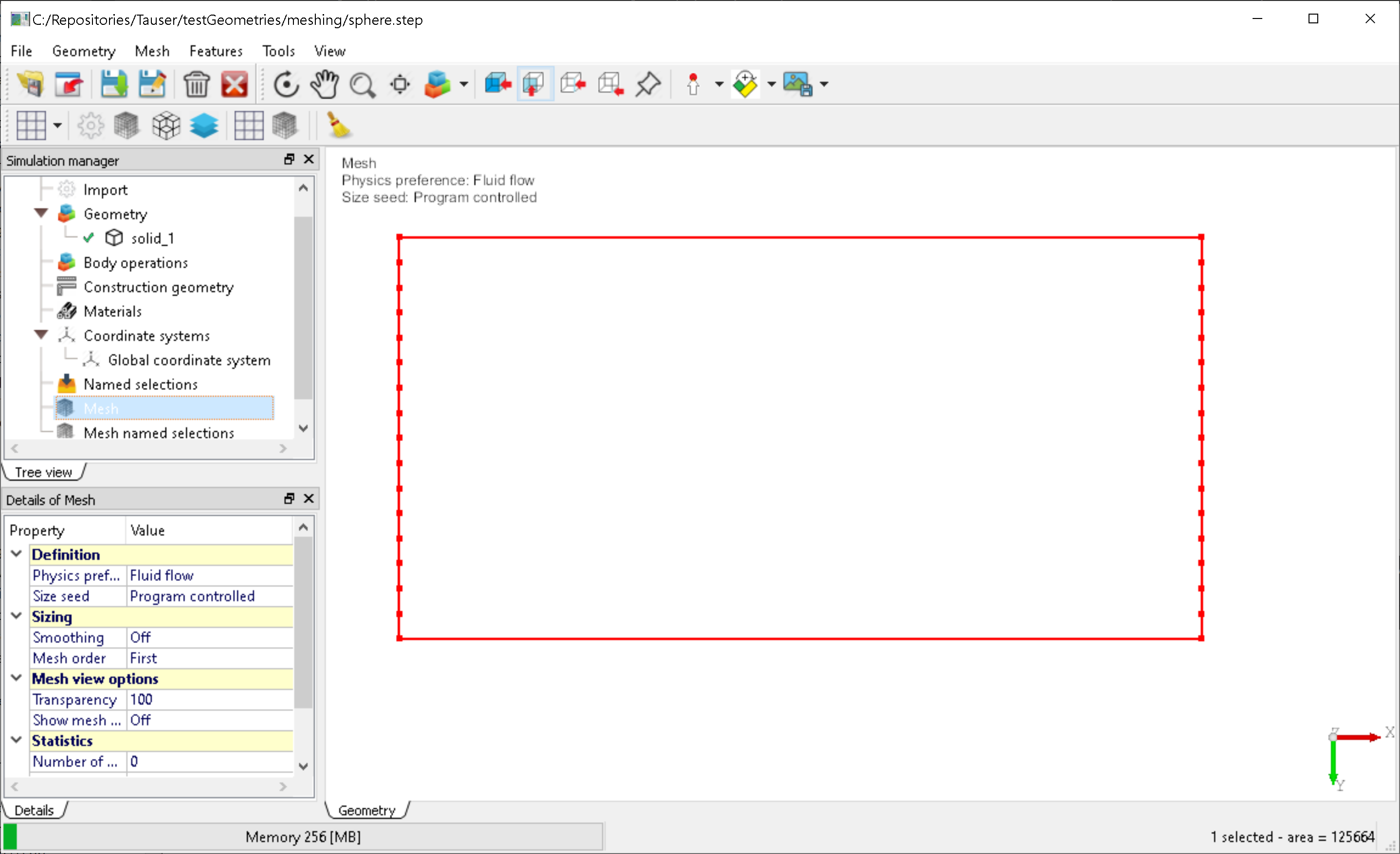
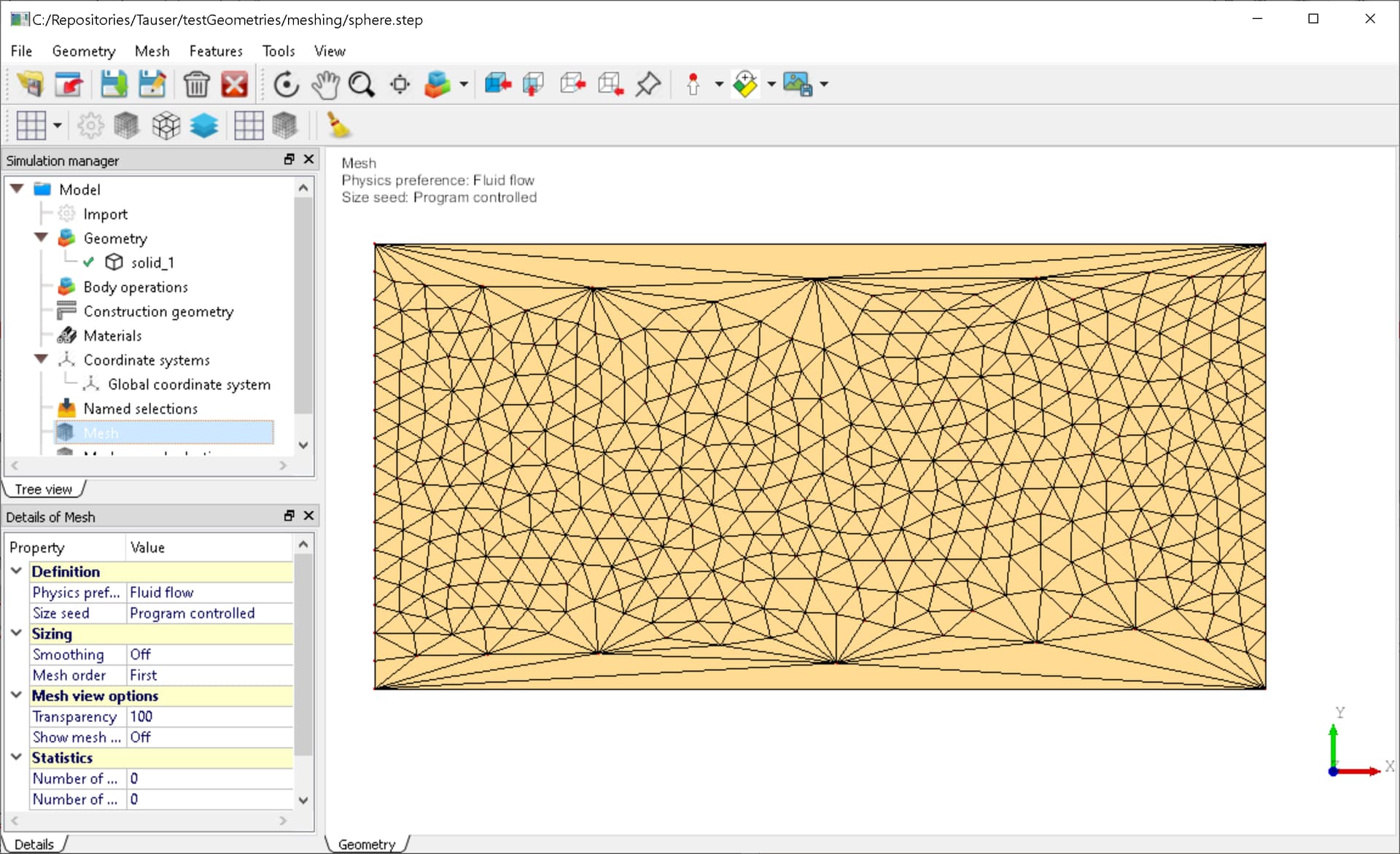
use this triangilation as “base” mesh for mmgs, with certain sizing parameters, (hmin, hmax, grading, …) applied locally, or globally, for obtaining a grid which is suitable for simulations. See the following figures Fig.1 and Fig.2.
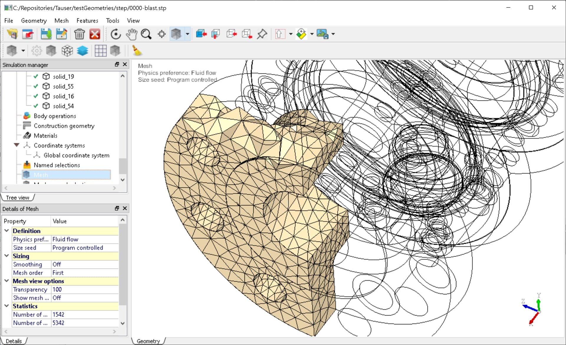
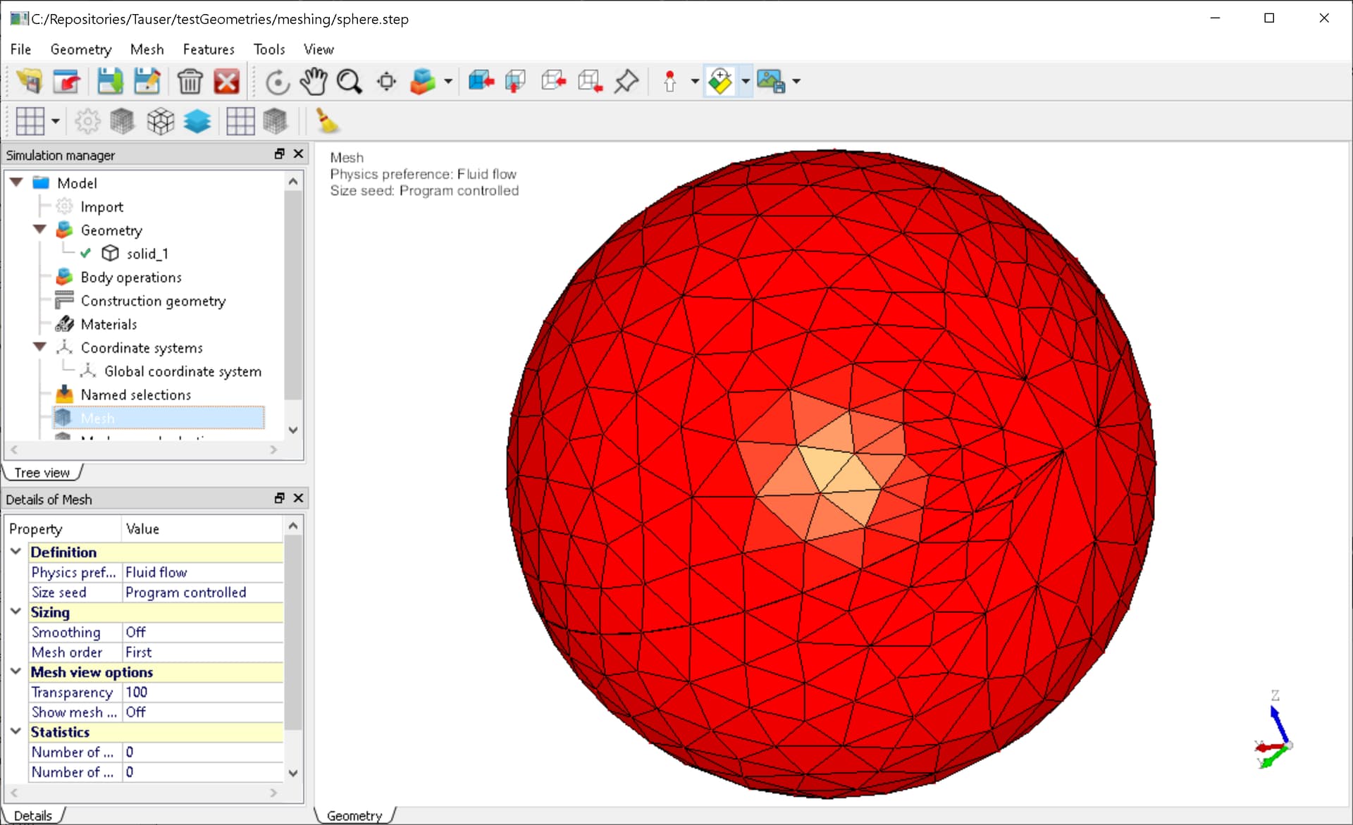
Then, from a surface mesh, in case of solid shapes, it is possible to generate a base tethaedralization, and refine it using mmg3D. It works See Fig. 3.
For certain reasons, which would be long to write about here, I would like to explore the following approach: nothing new, already done in literature.
I’m going to describe the approach with an example:
- consider a simple spherical face, as shown in Fig. 4, read from a .step file.
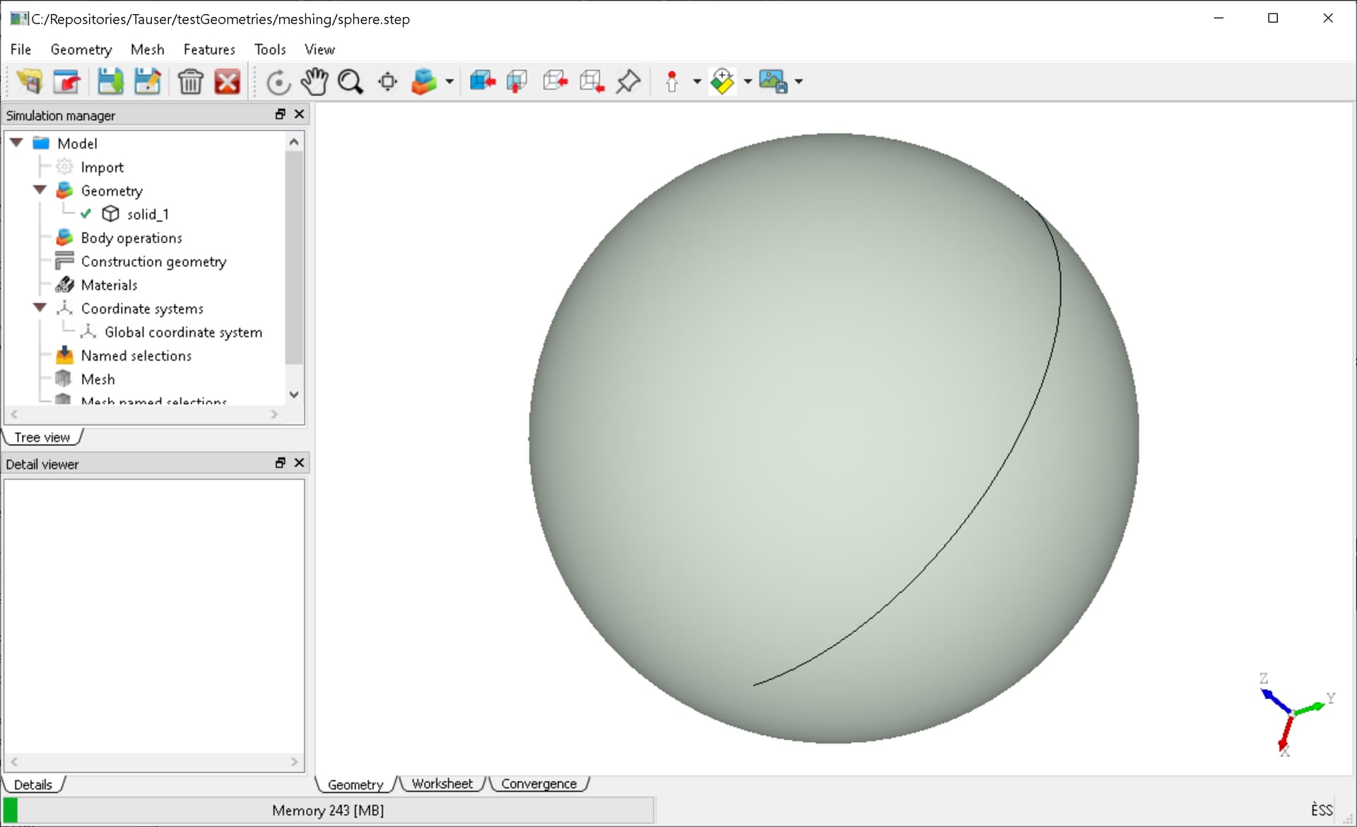
- in this case (I intentionally selected this one) we have two singular (degenerated) edges, the poles, and a seam edge.
Using a spherical coordinate system the poles are mapped onto the (u,v) plane as two straigth edges, and so the seam edge.
If the seam edge is discretized in 3d the boundary made of beams shown in Fig. 5 is obtained. Here the edge discretization has been performed using a fixed number of beams (N = 16)
- now I use mmg2d to generate a “default” triangulation of the rectangle, using a certain hmax. Notice that the edges of the (u,v) mapped face, are defined as => required <=. See Fig. 6
- finally, in order to obtain the 3D surface mesh of the sphere, the 2D mesh points should be re-mapped onto the 3D space using the inverse transformation. Opencascade does it very efficiently. See Fig. 7
This process is obviously general, and can be applied to other faces having different types of surfaces as support. It is robust, and fast, since mmg2d is fast.
Here the case is favourable, since the 3d mesh is not too bad. But as you has already thought the issue is that the (u,v) => (x,y,z) mapping introduces in general a “distorsion” in the resulting 3d mesh, if the faces to be discretized are curved.
I also mean that, if an user would like to discretize the sphere with a typical triangle size of 10, e.g. for a 100 radius sphere as the one in the figure, the 2d mesh must be generated with an anisotropic metric, which takes into account the metric of the surface.
Let be
| E F |
| F G |
the metric tensor of the surface.
For a sphere of radius
| cos(phi) 0 |
| 0 R^2 |
Now I come to the questions, that I ask you after several attempts.
Q1) Let suppose that the user would like to obtain in 3d space a typical edge size (element size) of L. The mesh in Fig. 6 can be used as a base mesh, and for each node one can use
MMG2D_Set_vectorSol(mmgSol,a11,a22,pos);
and finally remesh. Here which a1, and a2 should be such that the resulting mesh in 3d has elements of size L (istropic). Is this the suitable API function?
Q2) the lengths coming from the metric are 1/sqrt(l1), and 1/sqrt(l2), where l1, l2 are the eigenvalues of the E,F,F,G matrix. Which relations should be used for translating an isotropic mesh sizing in 3D to an anisotropic mesh sizing in 2D? Or, which are the right relatioships between a1, a2 and the desired length L (if the API call is the right one, obviously)
Grazie mille
Giovanni