Hello to all,
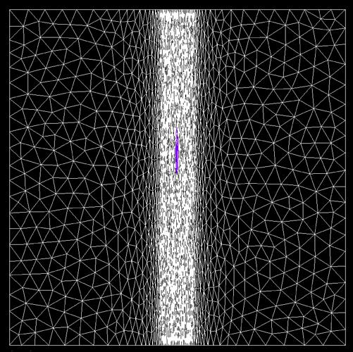
I have create a mesh using mmgs. I would like to modify the mesh refinement resolution using a know raster field.
1.Is it possible? and how ? practically, I would like to have more “dense” regions of triangles near to the strongest area of the field, and less to the other side. The current mesh using mmgs, give me a mesh with more triangles in the boundaries of the layer and less in the middle of it.
2. If the 1. could work, is it possible to create a 3D mesh, using the above mesh, in which:
the upper layer to be: the B.C.1 of a mesh which adapt the refinement of a raster1,
and
the lower layer to be: the B.C. 2. of a mesh that adapt the refinement of a raster 2 ?
thank you in advance,
John
Hello John,
Thank you for using the Mmg platform.
-
It is possible to provide to mmgs a metric field (i.e. a size map). For example, if you want an isotropic mesh (equilateral elements), you can provide on each node the size that you want for the edges passing through the node. Without this size map, mmgs keeps/adds nodes on high curvature area and deletes nodes on planar surfaces (to respect a maximal hausdorff distance between the “ideal surface” and the discrete one).
I am not sure to understand the “raster field” terms: do you mean a structured data field (like pixels)?
If yes, you must first interpolate this data on your unstructured mesh (the hard part of the job). Then you only have to compute a size from the node data (from your explanations and if you don’t have 0 values, something of the order of size = 1/data). -
We don’t provide tools for mesh generation but you can try with other open source software like Gmsh or Tetgen.
Regards,
Algiane
Algiane,
thank you for your answer and your help,
I am not sure how to provide a size map to mmgs to create my desired mesh; I need a further clarification,
also,
raster field yes it is a structure data field. About the interpolation of the field, do you mean to create 1 layer of points on max and min diff location?, and later how I will use it with mmgs? how I could compute the size of the node data ?
as for the Gmsh and Tetgen, my question was more about how the mmg3D tool could create a 3D mesh using three mmgs outputs 2D meshes. I though that it is possible,
thank you,
John
Hello John,
You must provide a size at each mesh node. To be able to compute it:
- you must know your field value at each mesh node. As you start with a raster field that applies on an unstructured mesh, I have supposed that initially, you didn’t know the field values at your mesh nodes.
I have made a small picture (2d) to explain what I mean:
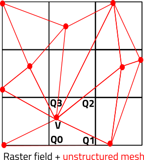
The black grid is your raster field, the red mesh your mesh:
- If you have 1 value per grid cell, you can simply find to which cell belongs a mesh node and set the cell value at the mesh node (so you set the value of the cell Q0 Q1 Q2 Q3 at the mesh node V).
- If you have one value per grid node, you must find to which cell belongs a mesh node (V belongs to Q0 Q1 Q2 Q3) and then compute the field value at the node V from its barycentric coordinates in the cell (l0,l1,l2,l3) and the values at the cell corners : field(V) = l0* field (Q0) + l1 * field (Q1) + l2 * field (Q2) + l3 * field (Q3 ).
2.Now that you have your field value at each mesh node, you must find a law that link this value to the wanted final mesh size. From your explanation, I think that you are looking for a law such as size = 1/field (you want a small size when your field is large, and a big size when it is small).
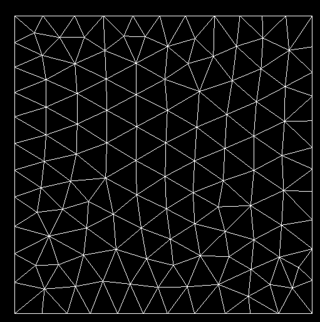
For example : I start form a squareInit.mesh (7.1 KB)
with edges of size 0.1 (I have apply a constant size map of 0.1 at each node)
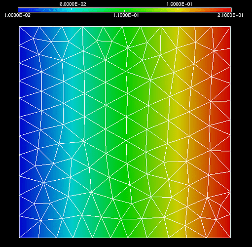
I compute a size field that evolve linearly in x: the size at a node (x,y) is s = 0.2*x + 0.01 (x is in [0;1]). This looks like this :
squareInit.sol (2.3 KB)
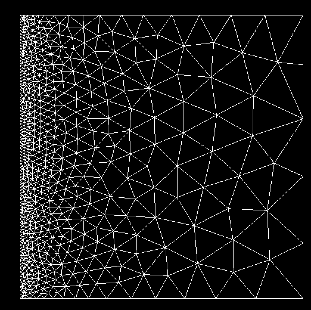
And I get my adapted mesh by running mmg2d :
To conclude : for now it is not possible to generate a mesh from mmgs surfaces with mmg3d.
Regards,
Algiane
Algiane,
thank you for your detailed and so informative answer. It was very helpful! I would like to clarify something in the second part. Lets assume that we study a river, and the raster field that we would like to use is the average depth integrated velocity, and lets assume the river flows from the right to left (concerning your plots in your illustration), and lets assume also that the river speed increasing from right to left. Then, the raster field, with x and y values in x and y direction respectively ( matrix ) will have higher values at the middle and near the left side. As I understand, the sol file is the file that include the information from the raster field, as the mesh file includes the info about nodes. If that it is right, please, how we could create or modify a sol file that include the river velocity in x and y direction? as in your example you use a 1D linear approximation (s = 0.2*x + 0.01 (x is in [0;1])). I assume, that we need to create a matrix for the sol file ? and if that is true also, how I could do that? do I have to just create ascii output ?
thank you,
John
Hello John,
There is lot of things in your questions…
-
About the file format:
Yes, the sol file contains, for each node, the size that we want to associate to the node and the mesh size the node informations. The file format are described here (in french). In short, if we look the squareinit.mesh/sol files :- The “Vertices” keyword in the mesh file says that we begin to describe the mesh nodes. It is followed by the number of nodes in the mesh (133). Last, we give the coordinates (in 2D: (x,y) ) and the reference of each node in the order of the node numbering (the node 1 has the (0,0) coor and the 0 ref, the node 2 has the (1,0) coor and the 0 ref…).
NB: Mmg does not use the reference field of the node (it is used for the triangles and edges to specify different domains/CFL) so you can forget about that, but it must be specified. - The "SolAtVertices" keyword in the sol file says that we begin to describe a solution/size at the mesh nodes. It is followed by the number of nodes (133, must be equal to the number of nodes in the mesh). Then we give the number of solutions that will be specified at each node (here 1 solution) and the type of each solution (1 for a scalar solution, 2 for a vectorial solution and 3 for a tensorial one). In our file, we have a scalar size field, so the second value (7th line) is 1. Last, we give the values of the solution at each node (0.01 is the value at the first node, 0.21 is the value at the second node…).
Solution file modification: - To save for example, the density and the velocity vector at each node, the 7th line of the file must be : 2 1 2 (2 solutions, the first one is scalar, the second one verctorial).
Then you must give the value of the density and the velocity at the first node (I suppose that we have a density of 1 and a velocity of (0.5,0.1): the 9th line became: 1 0.5 0.1.
Then the solutions at the second node (for example a density of 1.01 and a velocity of (0.4,-0.1)), the 10th line became 1.01 0.4 -0.1,
… - To give a size field to Mmg, you must have only 1 solution per node (the size field) and this solution can be a scalar field or a tensorial one (so the 7th line is 1 1 or 1 3). A scalar field means that you want an isotropic mesh (equilateral elements). It is the example that I have provided. A tensorial one means that you want an anisotropic mesh (edges with a preferential direction, which leads to non-equilateral elements). In this case, you must provide at each node a symetric definite positive matrix (2x2). As the matrix is SDP, you must provide only 3 values per node in your sol file: (m11, m12, m22). This matrix M can be diagonalized in M = tQ D Q with D the diagonal matrix of the eigenvalues and Q the matrix of the associated eigenvectors. If I note d an eigenvalue and q the associated eigenvector, the matrix M asks to have edges of length 1/sqrt(d) in the direction q.
An example of anisotropic size field: I start from a uniform mesh of a square with [-10;10]^3 bounding box, I ask for an isotropic size of 1 everywhere (so M is the identity matrix and in the sol file we have the values 1 0 1 at the nodes) except for nodes with -1<=x<=1 where we ask for an anisotropic size : the edges must be of length 0.05 in the x direction and of size 1 in the y one (M = ( ( 400 0 ) ( 0 1 )), and in the sol file we have the values 400 0 1):
squareInit_ani.mesh (975.4 KB)
squareInit_ani.sol (98.1 KB)
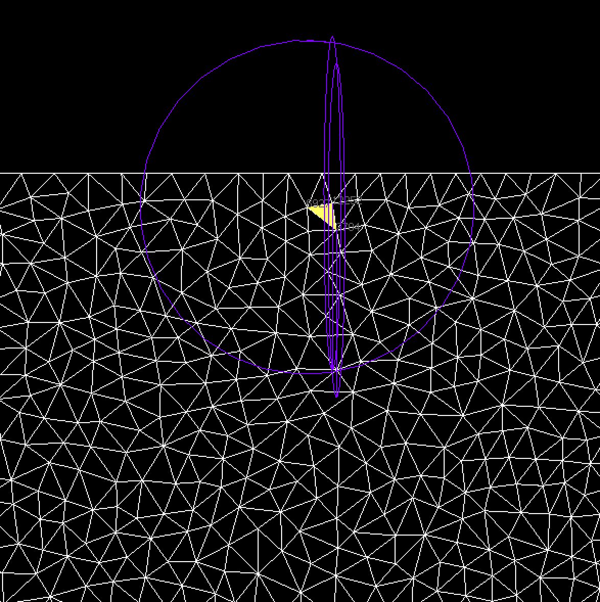
A zoom over the initial mesh and the metric tensor associated the the 3 vertices of a triangle (2 vertices have -1<=x<=1 and 1 has x < -1):
- The “Vertices” keyword in the mesh file says that we begin to describe the mesh nodes. It is followed by the number of nodes in the mesh (133). Last, we give the coordinates (in 2D: (x,y) ) and the reference of each node in the order of the node numbering (the node 1 has the (0,0) coor and the 0 ref, the node 2 has the (1,0) coor and the 0 ref…).
It gives the following result :
- About computing a size field from your velocity values:
- I am not sure to understand why you have a matrix and not a vectorial velocity?
- I don’t know what is usually done in the shallow water field but usually, to perform mesh adaptation, we use the following majoration of the error of interpolation (in 2D) :

Where u is a scalar solution interpolated over the mesh, Hu is the Hessian of u, K a mesh element and v the edges of the element K.
So we start from a scalar solution, compute at each node the matrix given by the right part of the inequality and provide this matrix as the anisotropic size field. To obtain an isotropic size field, we compute the sizes prescribed in each direction and apply the smallest one. - If I suppose that your velocity is a vector, you can:
- start from the norm of the vector
- compute the sizes prescribed by each field of the vector (independently) and intersect the resulting matrices (or take the smallest isotropic length that is prescribed).
Best Regards,
Algiane

