Is "exuding sliver tetrahedra" part of mmg3d features - here's a mesh where mmg gets stuck

Hello,
here: https://mathiasfuchs.com/sliverOut.mesh is a not too large mesh which seems to make mmg3d get stuck - the problem probably are some sliver tetrahedra but that it just my speculation! I might be wrong about the cause of the problem. Just the command

mmg3d.exe sliverOut.mesh

doesn’t finish - at least not after waiting for a few minutes, with the release build of mmg3d.exe from the latest develoment branch. The term “exuding sliver tetrahedra” seems to be the term papers use for this problem. Mmg seems to be trying to insert too many vertices. Why does mmg want to split so much? Which constraint is it fighting with? And what is the least permissive way to tell mmg to “be more chill” about that constrant, so that it come up with something. I need a finite element mesh, but at least the quality of the worst tet should improve.
I have tried out many possible combinations of settings that seem to relax some constraints, and rund with the “-d” flag, for instance:

mmg3d_O3 -d -hgrad 1000 -nr -nofem sliverOut.me

and other combinations of flags. Every time, mmg3d gets stuck splitting infinitely.

Cheers, Mathias
The input looks relatively harmless:

Hi,
Those slivers that I see (viewing in gmsh), are probably not just slivers, but also intersecting faces. This will cause mmg3D to fail for sure. You have to clean up that surface mesh and get rid of those. You can do that manually very easily in Blender. Or by whatever other software, or in your process.
Then I’m sure mmg3d will work as expected on this simple shape.
edit: if that is a 3D mesh (not surface), it’s possible that the original surface is funky, so fixing it also will involve fixing in whatever you used to generate the original mesh, prior to mmg3d.
Hope that helps,
Todd (abemis.com).

Thanks for the answer.
EDIT: I checked and there are no intersecting faces!
My question was the following:

Is exuding sliver tetrahedra part of mmg3d features?

This is a question about what mmg3d actually advertises itself as. Is the user expected to identify thin tetrahedra beforehand, or not?
By the way, of course I’m not interested in this particular mesh, I’m interested in the general way mmg works. This “flan” mesh is just the smallest example I could find where mmg does not finish. In any case, it might be a good feature of mmg if mmg could identify mesh failures beforehand, instead of hanging because I will not be the only user coming up with problematic input.

Hello Mathias,

Is exuding sliver tetrahedra part of mmg3d features?

I cannot answer to this exact question, but looking at the large geometrical size of the input mesh, I can manage to get some results with

mmg3d_O3 sliverOut.mesh -hausd 1000

(with or without -nofem)

So:

  • one problem seems to be related to the high coordinate values in the input mesh – although I always forget its implementation, the Hausdorff parameter should have a dimensional value (see -hausd – Mmg Platform), and the default one is way too small…
  • I also see some intersecting internal faces at the bottom of your model, although Mmg does not seem to be bothered by it.

I don’t know if this kind of adaptation pattern is good enough for your application, so the “is exuding sliver tetrahedra a feature?” question may still be pending :slight_smile:

Hope this helps!
Luca

Edit2: I also forgot to mention that the size of sliverOut.mesh is somehow wrong (500000+)? So that’s another issue to address when you remake sliverOut, etc.
Edit: I think I might have misstated a bit about the intersecting. I took another look, and what is likely happening is that sliverOut.mesh is not a proper FE mesh for some reason. I don’t know what you used to generate this initial mesh (did you mention? I might have missed it), but this often happens for me when I try to generate a mesh (I’m using CGAL) from a surface that has intersecting faces. But it could happen for other reasons too.
In my limited experience mmg3d cannot handle a topologically weird mesh such as sliverOut.mesh. In these screenshots I’ve highlighted the problems (in Gmsh, and loaded into Blender). For instance you can see that there is no node next to node 12, so that’s not a sliver, it’s called something else but I can’t remember off-hand. The whole mesh is pretty wonky.
You will have to redo sliverOut.mesh to get a better fully topo input mesh for mmg3d, or it’s not going to work and you’ll get that ‘infinite’ result that you mentioned.
Hope that helps!


— this info might still be useful for you to know —
HI, I have to say whatever you used to check is giving you a false response, if you are checking the tapered cylinder that you posted. I can show them to you, there are many. They might be connected in some way, that somehow subtly ‘passes’ your auto-check even though still not manifold. I’ve had that happen many times.

There are definitely no intersecting tetrahedra in the input mesh, I checked that multiple times.
Of course it is not a finite element mesh - mmg promises to remesh meshes such that they become finite element meshes, and this mesh is an input to mmg, not output. This input mesh is chosen by me deliberately to show that mmg sometimes runs hot instead of finishing, and to ask if mmg promises to deal with sliver tetrahedra or not. There is little point in dismissing the mesh as “wonky” - because it is deliberately chosen to be a bad quality mesh.
The point is that mmg should communicate with a helpful and constructive error message about what is wrong with its input, instead of just not finishing and running into an endless loop, and mmg should be clear about what it can do and what not. With this post I am trying to help users and developers of mmg by pointing out problems with mmg, not trying to mesh a flan.

Ok, so you are submitting an initial mesh that is so imperfect, that it causes mmg3d to fail. I don’t see why there is any reason to move ahead with this attempt to ‘break’ mmg3d.

By your argument; you could just make any incrementally further poor initial mesh, that is increasingly difficult to re-mesh. For mmg3d to work properly and efficiently, super-elongated slivers in the initial poorly generated mesh are your problem to solve. It’s fair to evaluate a software with an input that is ‘designed’ to break the process. I understand that, but I don’t see why mmg3d has any responsibility to resolve your specific problems with your broken initial mesh. That is your responsibility.

If you want to help improve mmg3d, then perhaps you should develop yourself a method to reduce or eliminate the obvious problems with your initial mesh. Can you do that?

I have done that, by pre-processing of our hyper-structures. We spent a lot of time/effort to ensure a manifold, sliver-removed initial mesh for our structures. If we can do it, surely you can too?

Look forward to your reply where you have fixed your problems. Again, I do not see this as a problem with mmg3D. It is your initial mesh that is the problem, and possibly a misunderstanding about how topologies work.

Hello,
My two cents: as I have recalled in my previous reply, the documentation says

By default, the Hausdorff value is set to 0.01, which is a suitable value for an object of size 1 in each direction. for smaller (resp. larger) objects, you may need to decrease (resp. increase) the Hausdorff parameter.

So my understanding and experience is that here Mmg goes into what appears to be an “endless” splitting loop because this input mesh has very large sizes (in coordinates), and the default Hausdorff value is too small. By setting it appropriately, Mmg terminates well on that case on my computer.

Have you checked the size of the mesh coordinates and the Hausdorff value for the other cases that get stuck?
If they continue to get stuck even with reasonable Hausdorff parameters, then we can move on blaming the topology handling in Mmg :slight_smile:

Bests,
Luca

I point out a problem with mmg and it is pretty outrageous that you attack me by saying I can’t “make a mesh that corresponds to the mathematics of the process”, and then you tell me I have an issue with “my understanding of the mathematics.”
Just for your information: I have a PhD in Mathematics and a solid academic track record (Academic publications Mathias Fuchs). I can certainly help but I’m not going to help people with such a bad attitude. By the way, I have already contributed quite a number of interesting discussions on this forum and I am contributor to mmg itself (commit 92c2b977664b5fa360b6db2e5aee902bc238c6ce which is in the master branch), just look it up. I’m going to report your post.

Yes, that kind of answers one half of the question, but that means that the default setting in mmg is wrong and needs to be replaced with a more appropriate setting. Moreover, you also throw a false accusation - that there are intersecting faces - which is not the case.

Hello everyone,

First of all, thank you all for your interest in this forum and in Mmg. This forum lives on thanks to you and your involvement and all the exchanges you have here can be useful to others.

If it’s all right with you, I suggest we take a short break on this subject while I read the exchanges: I’ll try to respond as best I can before the end of the week.

Best,
Algiane

Hello,

I will answer in multiple posts.

For the first post, I will try to answer to the main questions about Mmg.

1. Is “excluding silver tetrahedra” part of Mmg3d features?

Yes
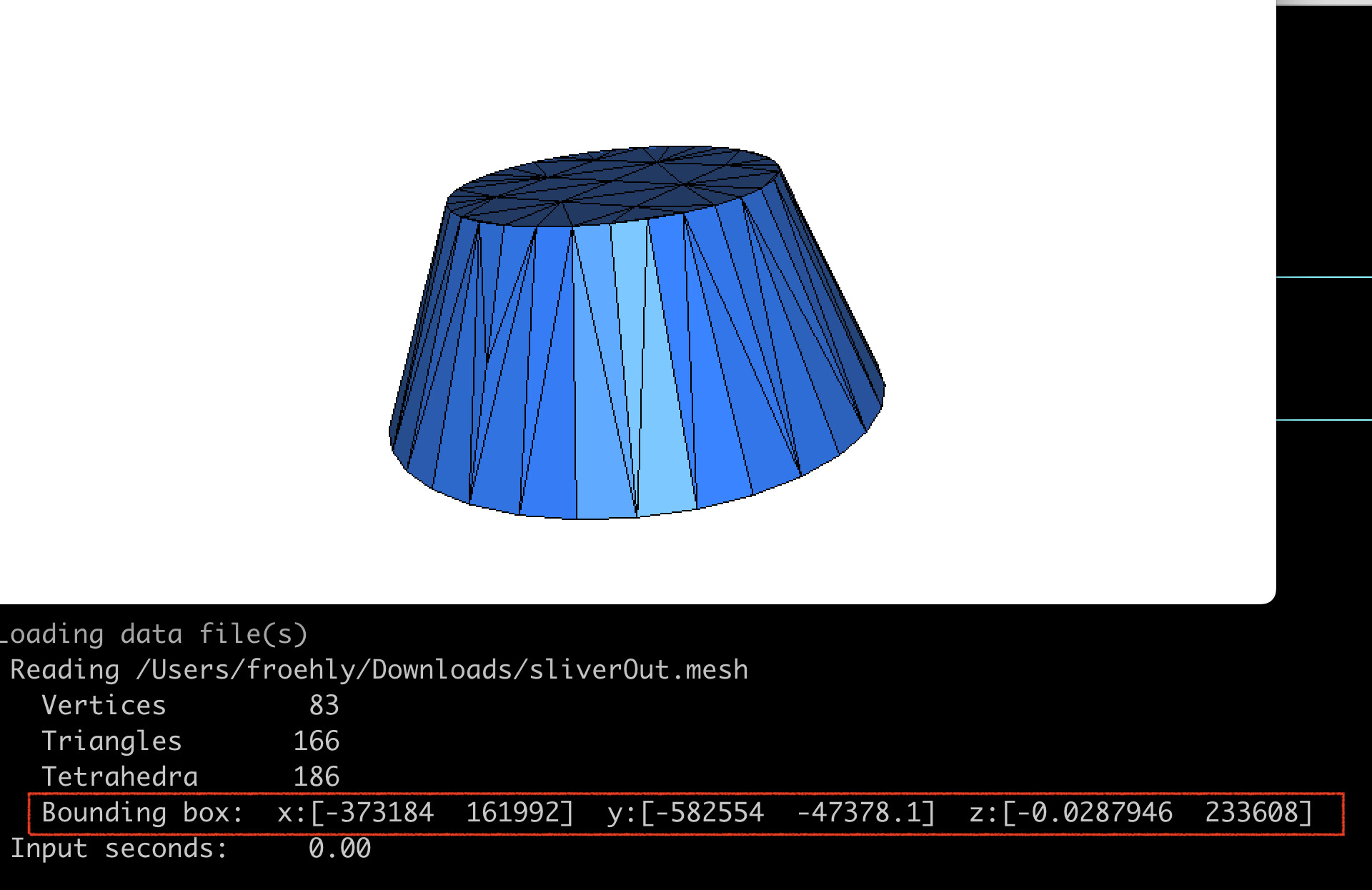
Mmg checks the volume of the input tetrahedra, raises an error message and stops if it detects volumes smaller than 1e-15. Thus, Mmg wil refuse to remesh a mesh containing input slivers.
We don’t want to start from lower volumes because numerical errors while reading/writing the mesh are becoming predominant.

2. Is Mmg checking the validity of the input mesh?

In a nutshell

Only partially
We don’t check the mesh conformity for example. For 3D surface mesh we also don’t check surface intersections…

But, for example, we check and try to fix issues in the provided boundaries of 3D meshes (triangle duplications, missing triangles…).

Why?

  1. There are lot of ways for a mesh to be erroneous and we just miss time to add those checks.
    Moreover, as we start from an existing mesh, the question/issue may be reported to the mesh generator: does it check the validity of the output mesh it returns?

  2. It is why we ask our users to try to provide a valid finite element mesh as input (but I know that it may be tricky to check).
    With a valid FE mesh, Mmg3D will return a valid FE mesh too or warn you and return an error value if it is not sure that the mesh is still a valid FE mesh (the main possible error inside Mmg is to end with a non-conforming mesh).

What happens if I start from a non-valid FE mesh?

The Mmg behaviour will be undefined:

  • in most of cases, the mesh will be successfully remeshed but you will end-up with a non-valid FE mesh of the same type or your input;
  • the code may fail during analysis;
  • the code may fail during the remeshing;
  • cases where the code livelock are pretty rare but may happen.

3. Why not set an absolute value for the hausdorff parameter?

Asking for an absolute value for the Hausdorff (I mean a value that doesn’t depend on the object size) has been tried but didn’t produce good results.
I am not sure if there were some numerical issues (It has been tried before I arrived on the project) but regarding the usability, I think that even with an absolute parameter, it is often necessary to manually change the default value (I will explain why after) and it is less intuitive to play with an absolute parameter than a relative one (the sensitivity of the absolute parameter is related to the object size and curvature due to the normalization…).

4. Why it is not possible for Mmg to set a suitable default value for the Hausdorff?

The hausdorff value you want to use depends:

  • on the size(s) of the object(s) you have inside your mesh;
  • on their curvatures (you will have no issue with the haudorff on cube meshes, whatever its value);
  • on the precision the user wants to approximate its boundaries.

It is just impossible to have a suitable value in some cases : for example, in fluid mechanics, there is often a very small object (let’s say an airplane), in a large bounding box (a sphere). In this case you want 2 hausdorff totally different on both surfaces because the hausdorff suitable for the bounding-box will lead to have almost no elements to represent the airplane, and the hausdorff suitable for the airplane will lead to refine a lot on the sphere surface.

5. Does Mmg guarantee to improve my mesh?

In a nutshell

No
“Improving” a mesh is a term that needs to be defined. The main aim of Mmg is not to improve the mesh quality but to produce an output mesh closer to the user’s needs than the input mesh. Of course, the element quality plays a role and we hope to have a sufficient minimal quality in our output mesh but we don’t try to “improve” the mesh quality.
In practice, what you need to run a computation on your mesh is a “not too bad” worst element (and the notion of “not too bad” depends on the numerical solver you use).

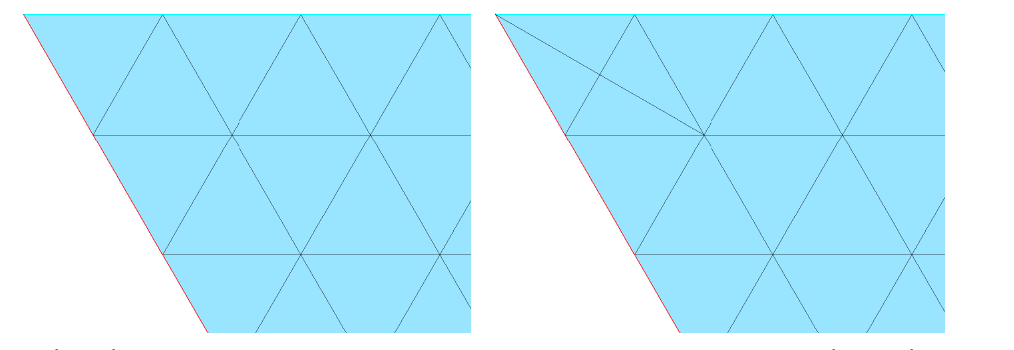
A very simple example that I like is provided in the following picture: the left mesh is “perfect” in term of quality (all elements are equilaterals) but it cannot be used in most FE solvers because one of the elements contains 2 boundary conditions. Mmg will produce the mesh on the right, which has a lower quality but can be used by all FE solvers: the quality is sufficient enough and all mesh elements have only one BC.

More details about the remeshing process

  1. The mesh adaptation process is an overconstrained problem: we try to have equilateral elements (in a metric space), to have a suitable boundary approximation (even in very curved area) that respect the geometric features and the topology, with a “minimal” number of elements and, in some case while respecting an input size map. To do that, every remesher make compromises and choose to favorize some of the previous criteria comparing to the others.
  2. The mesh adaptation process is also very heuristic: we interleave steps and operators (splits, collapses, swaps) hoping that it will produce a good result on a majority of the configurations. Each operator destroys the work of others (splits and collapses help to have suitable edge lengths but gives bad quality elements, swaps improve the quality but break the edge length…). It is the succession of operators that allow to obtain a mesh closer from the user prerequisite… but predicting that it will actually work before applying the entire sequence of operators is not so easy.
  3. Near boundaries, the respect of surface geometry and of the topology are huge constraints for the remesher and the generic local operations implemented may simply be inapplicable (because improving the mesh asks to pass by a step with negative volumes or with non local operators).

The algo implemented inside mmg is the result of the experience and work of researchers and we hope that it will give good results in most of cases (:wink: ).
But, depending on the test case, you may have better result with one remesher than another one, it doesn’t mean that one tool is better than the other, just that on the input configuration you provide, an algorithm behaves better than another.

In Mmg:

  • we give priority to the boundary approximation (because we start from an input discretization, if we lose boundary infos, we are not able to retrieve them). To have a suitable boundary mesh, we authorize to degrade the tetrahedra… and we have no warranty that we will be able to retrieve the input quality or to improve it;
  • we choose to produce a Finite Element mesh: by default we don’t authorize to keep boundary elements with more than one boundary face and, if possible, we split internal edges connecting boundary points (it has a consequence on the mesh quality too);
  • we authorize to degrade tetrahedra qualities because we have observed that it helps to unblock some bad situations. We hope to retrieve a better quality at the end but, again, we cannot ensure it.

I hope that it answers to the main questions about what can and can’t do Mmg. Do not hesitate to point me things that I may have missed.

For this second post, I will focus on the issue with the sliverOut.mesh mesh.

As pointed by @lcirrott , the issue is the Hausdorff parameter : your mesh is in the following bounding box:

 Bounding box:  x:[-373184  161992]  y:[-582554  -47378.1]  z:[-0.0287946  233608]

The Hausdorff parameter is relative to the mesh size so our default value (0.01) is too small and Mmg tries to create a very fine mesh. With a hausdorff of 100 I have a result in 3 seconds.

Some remarks on the input mesh:

  • it doesn’t contains elements with a volume smaller than 1e-15 (so it doesn’t contains slivers for Mmg) but it contains very small volumes (~1e-8) that can be considered as slivers in simple precision.
  • it is not a FE mesh: I am not sure but I think that it contains recovering tetrahedra (I will let you check your input). Mmg produces a non FE mesh in output too (because it doesn’t check that).
  • the output mesh quality is bad because the input mesh is not valid (Mmg adds boundary triangles that are almost co-planar due to the fact that it cannot build a suitable adjacency array and between these surfaces, mesh elements are too constrained).

How to check the mesh bounding box size ?

You can open .mesh files with the Medit mesh inspector. It prints in the terminal the mesh bounding box and allows to give an idea of the order of magnitude in which your hausdorff should be (see attached picture). A hausdorff of 1e-2 is suitable for a sphere of ray 1. Depending on your geometry, the size of the objects inside your mesh and your mesh bounding box you will have to adapt this value.

What can I do if I have a doubt on my input mesh?

With Mmg + Medit

  1. run Mmg in analysis mode with the sharp angle detection disabled (that means that you doesn’t allow Mmg to modify your mesh but it will perform the analysis step):
    mmg3d_03 -noinsert -noswap -nomove -nr sliverOut.mesh

  2. inspect the output mesh with Medit and print the geometric feature (g key). If Mmg has added unexpected “special edges” (orange or red lines), it means that there is something wrong in the adjacency relationships that Mmg has built.


    Note that the crossing triangles that we see are due to visual artifacts so it doesn’t help to determine if there are slivers or not inside the mesh.

  3. if you want to have more informations, you can inspect the boundary triangles by clicking them and deleting them with the s key: Mmg creates triangles only along tetra faces without adjacent (because you have 1 domain) so if you have weird recovering triangles, it means that there is an issue with the tetra adjacency relationships.

With other tools

I haven’t use it for a long time now but I remember that meshlab was a good opensource tool to check and fix meshes (but you will have to convert your mesh at another format, which can introduce errors).

Regarding the moderation demand: I think that we are just facing the difficulty of remote communications, moreover in a foreign language. This leaves a room for misunderstandings.

@Mathias-Fuchs : I agree that you have valuable contributions on this forum and it has always been a pleasure to discuss with you. I don’t think that your mathematical or scientific level is in question. @tcdoe has only tried to help.

I understand that there have been misunderstandings about the input mesh because it is a very weird mesh (something is wrong but it is not so easy to see what).

Edit:
@tcdoe : I will edit your post and remove the second sentence because it doesn’t change the meaning of the post and has hurt @Mathias-Fuchs.
@Mathias-Fuchs : I will keep the rest of the post because indeed, you will always find meshes on which Mmg will fail and you can create such meshes (at least, I can :wink: ). It doesn’t mean that I don’t agree with your approach: reporting bugs is helpful.
It allows other users to know that there is an issue and maybe someone will find the time to solve some of reported bugs in the future.

Best

@Algiane Thank you very much for the explanation posts. It will help me to debug some scenarios where we end up with sliver elements in the output meshes.