Cannot achieve improved tetrahedral mesh quality

Hello everyone,

I am new to Mmg and not a meshing expert either.

Context

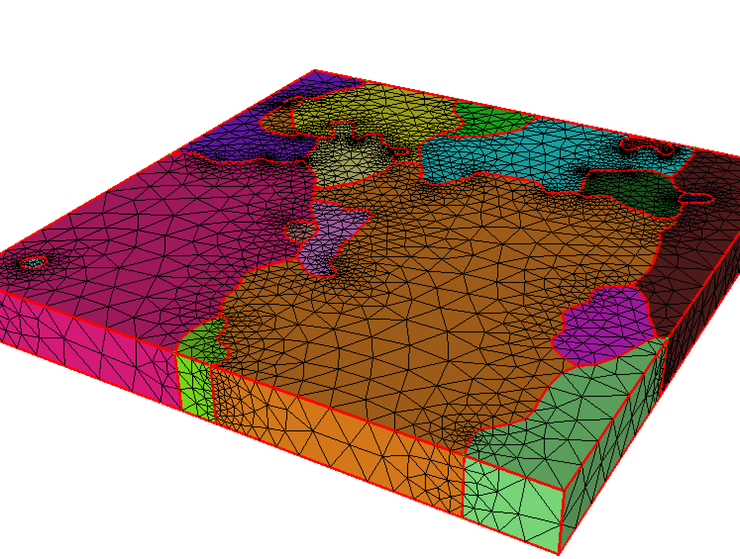
The mesh contains 18 disjoint sets of tetrahedra. They are called by different names in different programs (element groups, element sets, physical groups, subdomains, etc.). I will refer to them as element sets. These element sets represent discretized grains in a microstructure. I performed the mesh generation using the Netgen plugin to Salome, paying special care to generate as good mesh as I was able to. The difficulties I faced were the following:

  • I needed a relatively coarse mesh to be able to run a calculation within a reasonable amount of time.
  • The mesh needed to be fine enough so as to obtain not-so-high aspect ratios.
  • A minimum mesh density was vital so that the meshing does not fail at all.

I ended up with the mesh attached below.

Goal

  1. Improve mesh quality
    Even with the best mesh I could generate, it takes many Newton-Raphson iterates to achieve convergence in an elastoplastic simulation.
  2. Decimate mesh
    If I cannot improve the mesh quality by any means, I would like to make the problem size smaller by reducing the number of elements.
  3. Combination of both
    Apparently, the best would be the increase of element quality and coarsen the mesh at the same time. The reason for this is that the current mesh represents only a part of the original microstructure, so too many elements would be prohibited in the final application.

Constraints

  1. Do not erase subdomains
    It is important from the physics point of view to keep all element sets.
  2. Try to keep the boundaries
    There is an option for that in Mmg. If quality improvement is only possible by changing the boundaries, then I need to have means to quantify this discrepancy in order to have control over it.
  3. Do not lose information
    Whatever operations Mmg perform, I need to know which elements belong to which set in the modified mesh.

Ideas, and what I tried so far

  1. I read about the possible options, obtained by the --help flag, in the documentation.
  2. I tried the -hausd, and -hgrad options in different combinations. The results they produce make sense, but the quality (reported when passing the -v 4 option) is lower than that of the original mesh. Other quality metrics (available in Gmsh and Salome) also give lower values.
  3. I also tried the -optim flag to optimize the mesh. The quality became lower after the process.
  4. Generally, the elements in the input mesh have low aspect ratio. There are some elements though with not so good quality. Maybe I could concentrate on improving the quality of those elements only by local remeshing. Is this possible with Mmg, or is this a good idea at all?

Can you give me guidelines on how to approach this problem?
Thank you.
testMesh.zip (1.9 MB)

Hello,

Your problem is hard because you impose lot of constraints to the remesher:

  • you need a very good mesh;
  • your mesh is thin in the z-direction comparing to the other ones and has very few elements/nodes in this direction (the remeshing operators looses some freedom near the boundaries);
  • you have lot of boundaries that crosses and creates non-manifold edges: along these edges, Mmg must preserve the normals at the crossing surfaces and the edge tangent so improving (or not degrading) elements is hard;
  • this boundaries have high curvature area so sometimes, the elements are stuck between twe portion of surfaces.

A small tip : if your solver allows it, you can make the remesher job easier by authorizing the creation of elements with more than 1 boundary face (-nofem command line argument for “non finite element method” mode). By default, Mmg will enforce the splitting of such elements and it may degrade the mesh quality along the ridges (red lines in the visualization of your mesh that I attach).

Mesh quality

For Mmg (and I suppose for lot of meshers/remeshers) your input mesh is of very good quality (the average quality is of 0.79). I guess that it is the worst element that is annoying for you but it is not seen as a “bad quality” element by Mmg (its quality is of 0.23 and Mmg is happy when the worst element has a quality greatest than 0.1). I don’t know if you have tried to visualize it so I attach a picture.

.

Moreover the element is stuck along a boundary in a region of high curvature so the remesher doesn’t have lot of options to improve it.

A first solution:
Mmg is able to improve the worst element quality (from 0.23 to 0.28) if you run it in nofem mode (so elements with multiple boundaries are authorized), in optim mode (to compute a size map that matches the input edge length), and without boundary remeshing:

mmg3d_O3 -nosurf -nofem -optim testMesh.msh

Note that the number of tetra increases (121350->154834).

In fact, Mmg tries to create a good mesh but doesn’t check at each modification if the mesh is improved or not (quality degradation is authorized in the first waves of remeshing to give degrees of freedom to the remesher so he can target edge lengths and/or improve blocked configurations). It implies that on your good mesh, improvement is random (when you change the parameters of Mmg).

Mesh coarsening

I think that it is a better idea to try to coarsen the mesh.

Without surface modifications

You can obtain a mesh with less than 77000 tetra if you authorize volume coarsening (but the worst quality decreases to 0.14):

 mmg3d_O3 -nosurf -nofem testMesh.msh

If you increase the gradation parameter (-hgrad parameter whose default value is 1.3), you can coarsen the mesh but the element quality will decrease.

Normally, it is possible to run Mmg on its output mesh and metric to check if it is able to improve slightly the mesh but here, as the mesh contains very few elements, the gradation doesn’t converge and the second run creates a mesh with lot of additional elements.
You can pass through this issue by:

  • ignoring the metric file saved by Mmg in the second run: it requires to use the Medit file format at least for the intermediate step an to give a fake solution name to Mmg (for example fake.sol);
  • running in optim mode (-optim);
  • disabling the gradation (-hagrad -1, not recommanded in general);
mmg3d_O3 -nosurf -nofem testMesh.msh tmp.mesh
mmg3d_O3 -nosurf -nofem tmp.mesh -sol fake.sol -optim -hgrad -1 testMesh.o.msh

The output mesh has a quality of 0.20 and 90000 tetra.

With surface modifications

Surface modifications will give more DoFs to the remesher.
In this case you must take care of 2 parameters: the hausdorff (-hausd, that will densify the mesh in curve areas and coarsen it in plane ones) and the sharp angle detection (-ar):

  • on your geometry you need to detect the cube ridges but to avoid sharp angles so a good value to provide for the ridge detection is 90. Note that you can also provide the cube ridges and disable the sharp angle detection with -nr;
  • your mesh bounding box is small so you need a small hausdorff, the value 0.0005 allows to keep almost the same surface parametrization than the input one but you can increase it slightly to coarsen the surface.
mmg3d_O3 -nofem -hausd 0.0005 -ar 90 testMesh.msh

creates a mesh with 63000 tetra and a worst quality of 0.15.

If your curved boundaries needs to be preserved, you can also provide input triangles and specify the “interior” boundaries as required, so the cube surface will be remeshed but not the other surfaces.

I hope that it will help.

Regards,
Algiane

Thank you for the well-structured and detailed response. I am asking for some clarifications:

  1. I observed similar element number and quality changes using the various commands you gave, but not quite the same numbers. Is it because we use different versions off MMg (mine is MMG3D, Release 5.5.2 (Nov. 17, 2020)) or there is some randomness in the algorithms?

  2. Could you elaborate on the definition of the Hausdorff distance in the documentation? I would need an understanding on the following three terms:

    • I call input mesh boundary, \Gamma_i, the piecewise linear boundary (segments for 2D meshes, triangles for 3D meshes) between two neighbouring subdomains of the input mesh.
    • I call modified mesh boundary, \Gamma_m, the piecewise linear boundary obtained by modifying \Gamma_i during the remeshing procedure.
    • Reconstructed ideal boundary (let us denote it by \Gamma_r), mentioned in the documentation.

    How is \Gamma_r defined, and how is it computed?

  3. By surface modification, do you mean modifying a boundary part? Does the -nosurf flag mean that the Hausdorff distance is zero?

  4. Can the topology change (e.g. vanishing subdomains) if a large Hausdorff distance is given by the user, or does Mmg guarantee that this does not happen?

  5. If surface modification is enabled, what quantifies the distance between the original boundary and the boundary of the modified mesh? I have no objection against modifying the boundary, but then I should be able to quantify that change. The Hausdorff distance would make sense, but can Mmg compute it upon request? What I am thinking of is the following:

    1. The user does not explicitly provide the value of -hausd, only sets other parameters (-hmin, etc.) or no parameter at all (hence, relying on Mmg’s default values).
    2. The user calls mmg3d, which returns a modified mesh.
    3. The user would like to know, preferably for each boundary part, the Hausdorff distance (or any other relevant metric) that allows him to see how much the boundary has changed during remeshing. I find this important because too much boundary distance between the original and the optimized mesh means that we do not represent well the original geometry (on which the original mesh was created) any more.
  6. you have lot of boundaries that crosses and creates non-manifold edges

    What do you mean by non-manifold edge? Could you show me a zoom on the part where it occurs?

  7. on your geometry you need to detect the cube ridges but to avoid sharp angles so a good value to provide for the ridge detection is 90. Note that you can also provide the cube ridges and disable the sharp angle detection with -nr

    What is a cube ridge? Where the angle between two neighbouring boundary elements is 90°?

    If your curved boundaries needs to be preserved, you can also provide input triangles and specify the “interior” boundaries as required, so the cube surface will be remeshed but not the other surfaces.

    Just to make sure I understand: if I provided all the boundary triangles (i.e. along the internal and external boundaries), would that be equivalent to giving the -nosurf option? Do I need to speciy the triangles in an external file?

Best regards,
Zoltan

Hi,

  1. We have random computations in mesh generation mode (2D) only. Otherwise the results are reproductible but they depend on the memory of your machine (we authorize the use of 50% of the RAM of the computer. If Mmg doesn’t have enough memory to create a new point, it can try to collapse too long edges first). This behaviour may be controlled using the -m option.
    We probably have different results because I have local modifications in my version of Mmg (;-)).

  2. Ok, I will develop the documentation on the website: \Gamma_r is a cubic piece of surface (Bézier cubic polynomial) reconstructed from a triangle and the normal at the triangle vertices. The reconstruction is described in C. Dapogny, C. Dobrzynski and P. Frey – April 1, 2014 – JCP, 262, pp. 358–378. The hausdoff distance can be seen as the maximal distance between the “flat” triangle and the “curved” one.

  3. Yes, by surface modification I mean that the surface discretization is modified. But when we modify the mesh, we try to stay close from the model underlying the geometry and to preserve the different regions of the mesh.
    The -nosurf flag means that the surface triangulation can’t be modified (as in Constrained Delaunay Triangulation) so you will recover the boundaries that you have provided except that the triangles numbering may be modified.
    The hausdorff distance is 0 only if all your mesh boundaries are plans (like in a cube mesh for example). We can’t maintain a 0 hausdorff distance if you have curved boundaries (because it implies to insert an infinity number of points along the curve).

  4. We try to check that subdomains doesn’t vanish but there are very few configurations for which it is not possible to check the preservation of the mesh topology. Thus it is always recommanded to have reasonable hausdorff parameter. An exception is the optim mode because you stay close from your input surface. Otherwise, with a large hausdorff, you authorize the remesher to coarsen your surface in its first waves. The main risk is to loose precision on the boundary approximation.

  5. We don’t quantify the distance between the input and final mesh but I understand your concern. One reason is that the surface remeshing was initially implemented to allow to perform isovalue discretization (for topology optimizations) so without having an initial surface mesh.
    Another reason is that your initial mesh is only an approximation of your geometry so either you forbid any surface modification (-nosurf option), either the remesher has to try to recreate the underlying surface.

  6. Non-manifold edges are edges shared by more than 2 boundary triangles (all the internal red lines on the mesh). Such area are harder to remesh due to the presence of the surfaces (and we must preserve some geometric feature such as the normal direction for each piece of surface, the tangent direction of the non-manifold edge, etc…).

  7. Yes, by ridge I mean an edge that delimits 2 portions of surfaces that intersects with a sharp angle (90° for the cube but Mmg detects ridges from 75° by default). The surface model is not smooth anymore along the ridge and, for example, if we need to compute the normal at a node, we take into account separately the 2 portions of surfaces and we compute 2 different normals, one for each side of the ridge. In Mmg you can decide which angle define a sharp angle (-ar <float> option) or disable this detection (-nr option).
    Indeed, providing all the boundary triangles as required is equivalent to the -nosurf option.
    You can specify the triangles in your input file (but at Medit file format, not at the Gmsh one) or using API functions.

How to set triangles as required
As you use Gmsh, you need first to create “physical surfaces” with different physical tags for the cube boundaries and the other one (so the remesher can detect that a triangle belongs to one or the other surface). Lets guess that the cube boudaries have the tag 1 (a reference for medit) and that the interior boundaries have the tag 2.
Then you can travel your surface triangles and mark as required those ones that have the reference 2:

  • directly by modifying Mmg (fast if you don’t have lot of time but you will need to remove these modifications for other test cases). For that, you can add the following lines in the MMG3D_loadMshMesh function (mmg/src/mmg3d/inout_3d.c), after the call to MMG5_loadMshMesh_part2:
int k;
for ( k=1; k<=mesh->nt; ++k ) {
  if ( mesh->tria[k].ref == 2 ) {
    mesh->tria[k].tag[0] &= MG_REQ;    
    mesh->tria[k].tag[1] &= MG_REQ;
    mesh->tria[k].tag[2] &= MG_REQ;
  }
}
  • by creating a small program that will convert your mesh at Medit file format and will mark the wanted triangles as required using the Mmg APIs. You have examples of library call in the mmg/libexamples directory. Something like the following should work:
MMG5_pMesh mmgMesh = NULL;
MMG5_pMesh mmgSol  = NULL;

MMG3D_Init_mesh(MMG5_ARG_start,MMG5_ARG_ppMesh,&mmgMesh,MMG5_ARG_ppMet,&mmgSol,MMG5_ARG_end);

/** Load Gmsh mesh */
if ( MMG3D_loadMshMesh(mmgMesh,mmgSol,"testMesh.msh") != 1 )  {
  exit(EXIT_FAILURE);
}

/** Get mesh size (to recover the number of triangles */
int np, ne, nt, na,
if ( MMG3D_Get_meshSize(mmgMesh,&np,&ne,NULL,&nt,NULL,&na) !=1 )  
{
  exit(EXIT_FAILURE);
}

/** Mark as required the triangles of ref 2 */
int k,v[3],ref;
for ( k=1; k<=nt; ++k {
  if ( MMG3D_Get_triangle(mmgMesh,&(v[0]),&(v[1]),&(v[2]),&ref,NULL) != 1 ) {
    exit(EXIT_FAILURE);
  }
  if ( ref == 2 ) {
    MMG3D_Set_requiredTriangle(mmgMesh,k);
  }
}

/** Save the mesh at Medit format */
if ( MMG3D_saveMesh(mmgMesh,"testMesh.mesh") != 1 ) {
    fprintf(stdout,"UNABLE TO SAVE MESH\n");
    return(MMG5_STRONGFAILURE);
}

/** Memory release */
MMG3D_Free_all(MMG5_ARG_start,MMG5_ARG_ppMesh,&mmgMesh,MMG5_ARG_ppMet,&mmgSol, MMG5_ARG_end);

Regards,

Algiane

Thank you, now I understand.
Could you please leave this discussion open? Priorities have changed, so I need to run simulations on the current mesh. However, I want to improve that mesh later using your suggestions.

I will let this discussion open.
Have a nice day.