How to keep original region label after MMG update

Dear developers,

I met a problem when using MMG2d/3d to update mesh based on the level set function.

My original mesh contains 3 regions, with different region labels, as below:

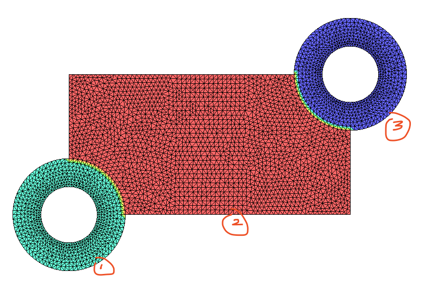
Then I use the following command line to update the mesh based on the level set function:
mmg2d_O3 ./LvSet.mesh -sol ./LvSet.sol -ls -nr -hmax 8.0e-3 -hmin 5.0e-3

After that I checked the region label again, and found that the mesh was merged into a big region, as below:

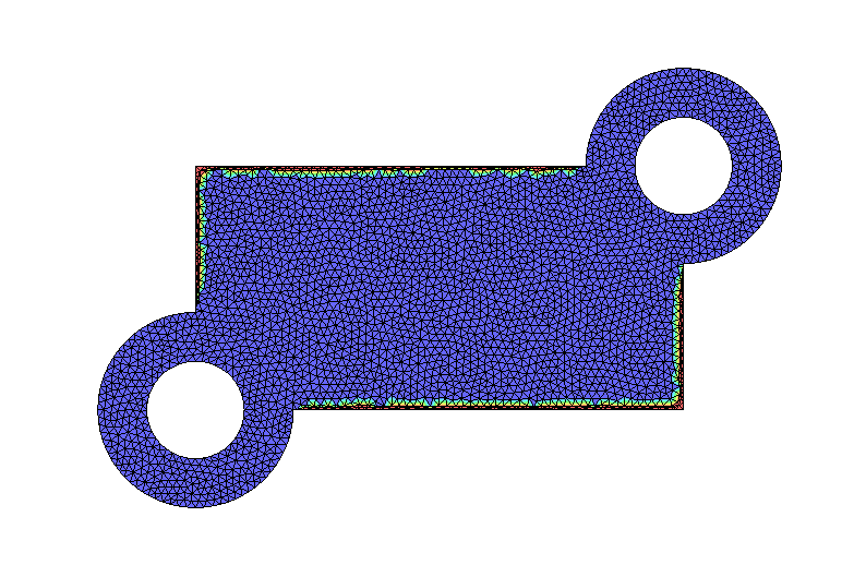
So, would it be possible to keep the original region label after MMG2d/3d?

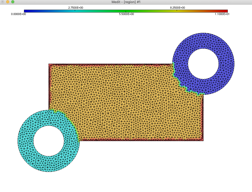
I uploaded the original mesh, and level set solution file. Please check.

Sincerely yours,
HaoLvSet.mesh (237.2 KB) LvSet.sol (12.0 KB)

Hi,

By default Mmg erases the input regions to create the 2 new regions defined by the level-set (this new regions are labelled with references 2 and 3).

In 2D, the develop branch of Mmg allows to provide to Mmg an additional file (of same basename than the mesh but with .mmg2d extension) that contains the input references and their mapping on two new references (it is not yet implemented in 3D and the API aren’t available but it is planned for the end of the year). I detail here how is made the LvSet.mmg2d (37 Bytes) file and I attach it so you can directly test the reference mapping:

LSReferences
3
10 11 10
4 5 4
0 1 0
  • LSReferences means that we will define the reference mapping during the level-set discretization;
  • 3 is the number of input references for which we provide a mapping;
  • 10 11 10 means that the domain 10 become the domains 11 and 10 if splitted by the level-set (to map the reference 10 onto 11 and 12 we must write 10 11 12);
  • 4 5 4 means that the domain 4 become the domains 5 and 4;
  • 0 1 0 means that the domain 0 become the domains 1 and 0;
  • Note that you can also ask to not split a given domain even if it is intersected by the level-set: 10 nosplit forbid the splitting of the domain 10.

I hope that it will be sufficient for your current needs.

Best,
Algiane

question. Does this only affect to the develop branch?

Yes, I think that it works, but I was not sure that the master version is fully up to date (but it seems).

Best

Therefore I will need to update the implementation…

Dear Algiane,

Thanks for your very helpful note, I have tested your reference mapping, and it works well. Now the new mesh (after MMG2D) has kept the original region number, as below:

May I confirm with you about LSReferences?
4 5 4 means that domain 4 become domains 5 and 4;
0 1 0 means that domain 0 becomes domains 1 and 0;

And I check the region label and found that domain 4 and 0 remain 4 and 0. There is no domain 5 and 1.
Is this because the domain 4 and 0 are not splitted by the level set?

And we are looking forward to the latest version at the end of the year. We hope this feature will be available in MMG3D, together with MM3D parallelization.

Best regards,
Hao

Hi,

Yes, the line 4 5 4 means that if the ref 4 is splitted by the level-set, the negative part of the level-set becomes the ref 5, the positive one the ref 4.

A small remark: the first release of the parallel library will only provide parallel mesh adaptation and only inside the volume (ther is some additionnal work to do for the surfacic interpolation and the parallel analysis of geometric feature). Once the parallel surface remeshing will be ready, adding the level-set discretization will be very easy.

Best,

Hi,

If you can wait few weeks we plan a release for December (before the Mmg day).

Regards

Dear Algiane,

Thanks for your answer and small remark. Sure, we are waiting to hearing from you.

Best regards,
Hao

Dear Algiane,

is this feature of user label preservation now available in mmg3d ?

Sorry for re-opening an old topic.

Best regards,
Chiara

Dear Chiara,

For now it is available in the feature/multi-mat3d branch (Charles and I are still investigating some quality issues). We would be happy to have your feedback on this feature!

You will find an example of usage here: Offset mesh surface

Regards,

Algiane

Hi Algiane,

thanks a lot for your reply !

I tested the feature on a toy exemple with 2 materials and the preservation of tetrahedral tags is correctly handled. However I have a surface triangulation with a given label (say, 96) at the interface between my two materials; the surface 96 is kept but its label is changed to 10. Would it be possible to preserve also the tags on surfaces, at least when the level set does not cut them ? If you have multiple materials usually you want to impose some transmission boundary conditions at the interfaces.

Also it could be very nice and useful to have a feature “required tetra” (as it is already done for edges and triangles) to keep a given region unchaged during the remeshing.

Thank you in advance for your reply

Hi Chiara,

I have tried to discretize an implicit surface in a multidomain mesh (with an interface between the initial domains not equal to 10) and it seems to be preserved in my case.
I attach the input mesh, the cube-with-tube-ref1.mmg3d (32 Bytes) and the cube-with-tube.sol (462.5 KB).
The input mesh contains only triangles of ref 1. I run my test case with the following command line:

mmg3d_O3 -ls cube-with-tube-ref1.mesh -sol cube-with-tube.sol -nr -ls 0.5

Maybe have I not understand your issue?

Regarding the required entities: you can provide required tetrahedra in mesh adaptation mode. In isovalue discretization mode it is also possible but only if the input level-set doesn’t intersect the required tetrahedron (it is ignored otherwise).

Regards,

Algiane

Hi Chiara,

Just to complete my answer: there was a bug when the level-set was intersecting a required tetra (that make Mmg fail). It is fixed by commit bae70ae73c: in this case, the required tetra is splitted by the level-set but it is not remeshed after that step (so the sub-tetra created by the split are preserved).

Regards

Dear Algiane,

you understood perfectly my issue. I tested your data and It works well but not with my test case.
I attach the input mesh (in.meshb )

https://irtsystemx-my.sharepoint.com/:u:/g/personal/chiara_nardoni_irt-systemx_fr/EYIZgUULp-FDuTsxbvP9xSsBNYgV2SBQoc0RJVoWqLe4pA?e=CAE18K

the input level set (in.solb) in.solb (500.0 KB) and the mmg parameter file (in.mmg3d) in.mmg3d (30 Bytes) .
I run with the following line :

 mmg3d_O3 in.meshb  -nr -ls

and it seems to me that the original surface tag 96 is converted to 10. Please see if you find the same.

Just to be clear I use the following code

git branch: feature/multi-mat3d
 git commit: 59bcd0e5261504d8a43a6d835ab63fbf842fce63
 git date:   2020-09-30 10:23:24 +0200

For the required tetra: great, i didn’t know ! Can you please remind me which is the keyword to use in the mesh file ?

Thank you a lot in advance for your help !

Dear Chiara,

It is an input issue: I don’t know why, Mmg doesn’t detect the triangle field in your binary file. I am not sure if it comes from our side or from yours: how did you generate your file? using the libmesh library?

When reading your file Mmg jump from keys to keys to read the number of entites of each type. We detect: the dimension key, then the vertices one, the tetra one and the end key.

Thank you by advance for your answers.

Algiane

Dear Algiane,

I use internal tools to write the mesh.
I verified and effectively I don’t have the triangle field in my mesh. I can visualize it using medit but maybe it is a medit issue. I will test if it works correcly when I add the skin.

But on my original input (no skin provided) I don’t understand why mmg discretise the interface with a label 10 (the level set is not zero at the interface between the two materials !).

Thank you for your answer

Ok,

Medit builds automatically boundary triangles from tetrahedra if no triangles are provided (I had forgotten this fact too). It can be disabled by running Medit with the -s option.

Have a nice evening.

A.

Ok, now I also understand why a surface 10 is created !

Have a nice evening too