Implicit mesh adaptation in a region

Hi,

I’m using mmg3d to adapt my mesh to a level-set function. I’m trying to follow the tutorial, however I have some specific needs here that I fail to satisfy.

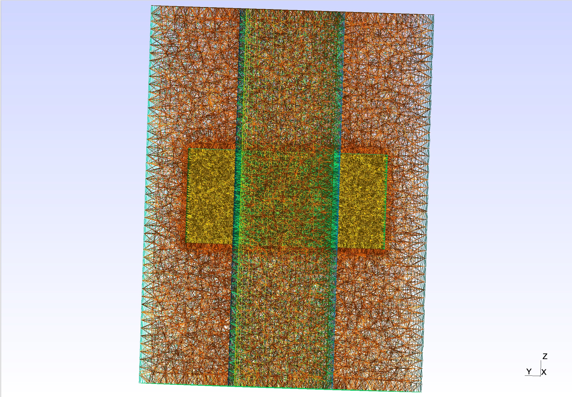
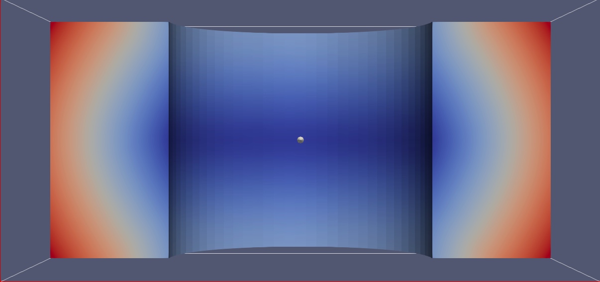
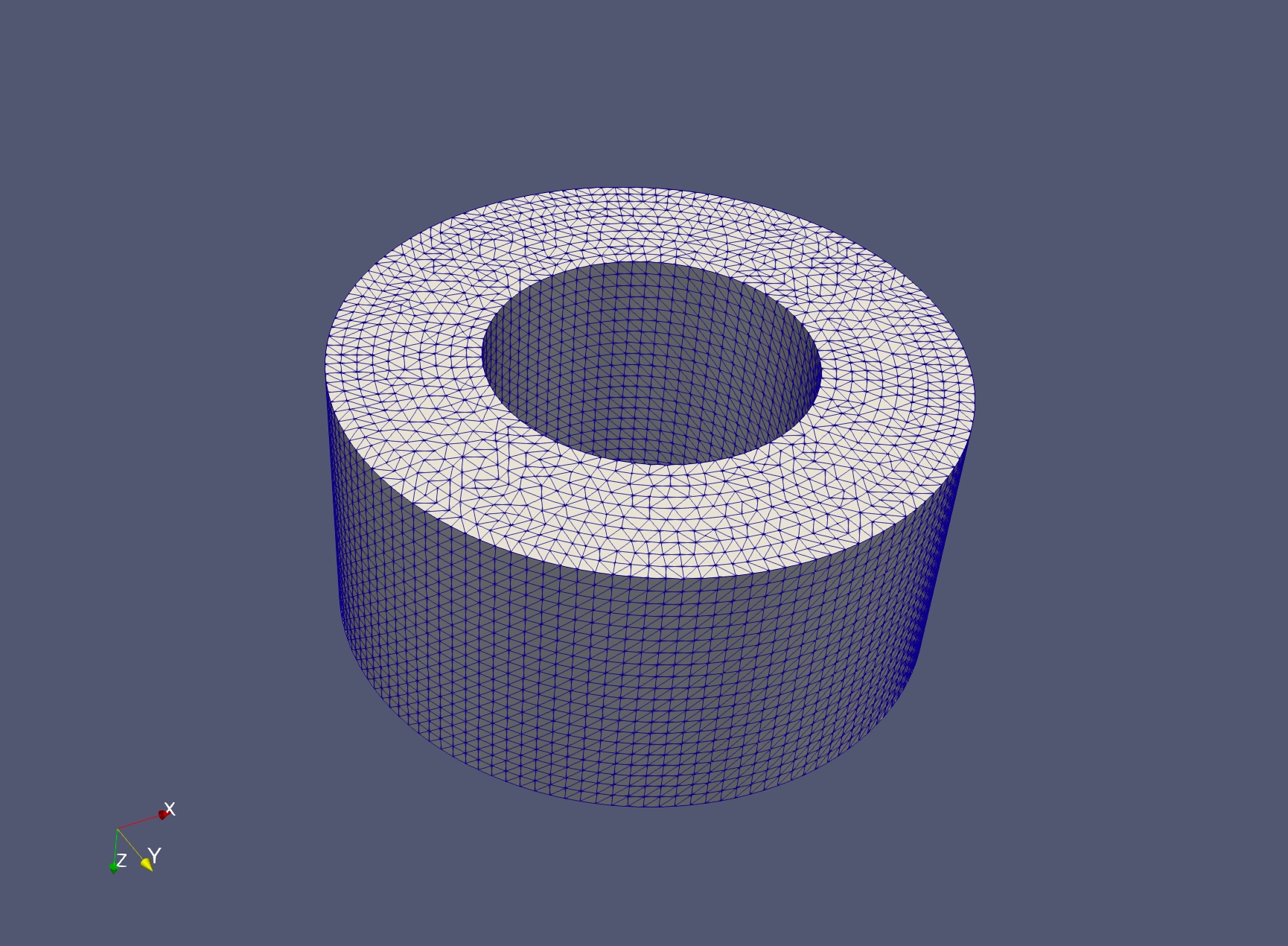
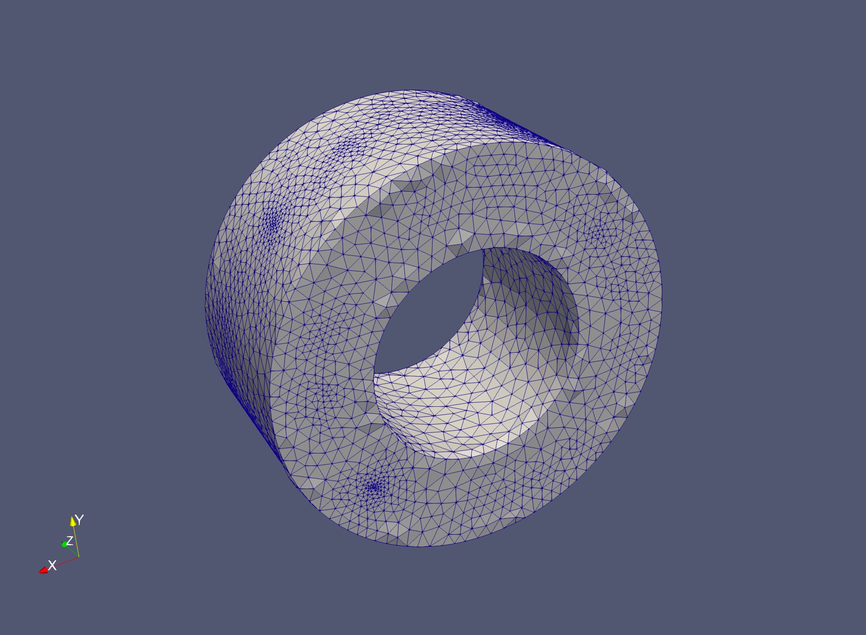
I consider a cylindrical mesh that consists of two tube walls and a ring around a specific region of the outer tube wall. I define my level-set function inside the ring : I aim at adapting the mesh inside the ring with respect to the level-set function. However I cannot find a way to do it with mmg3d, do you have any idea ?

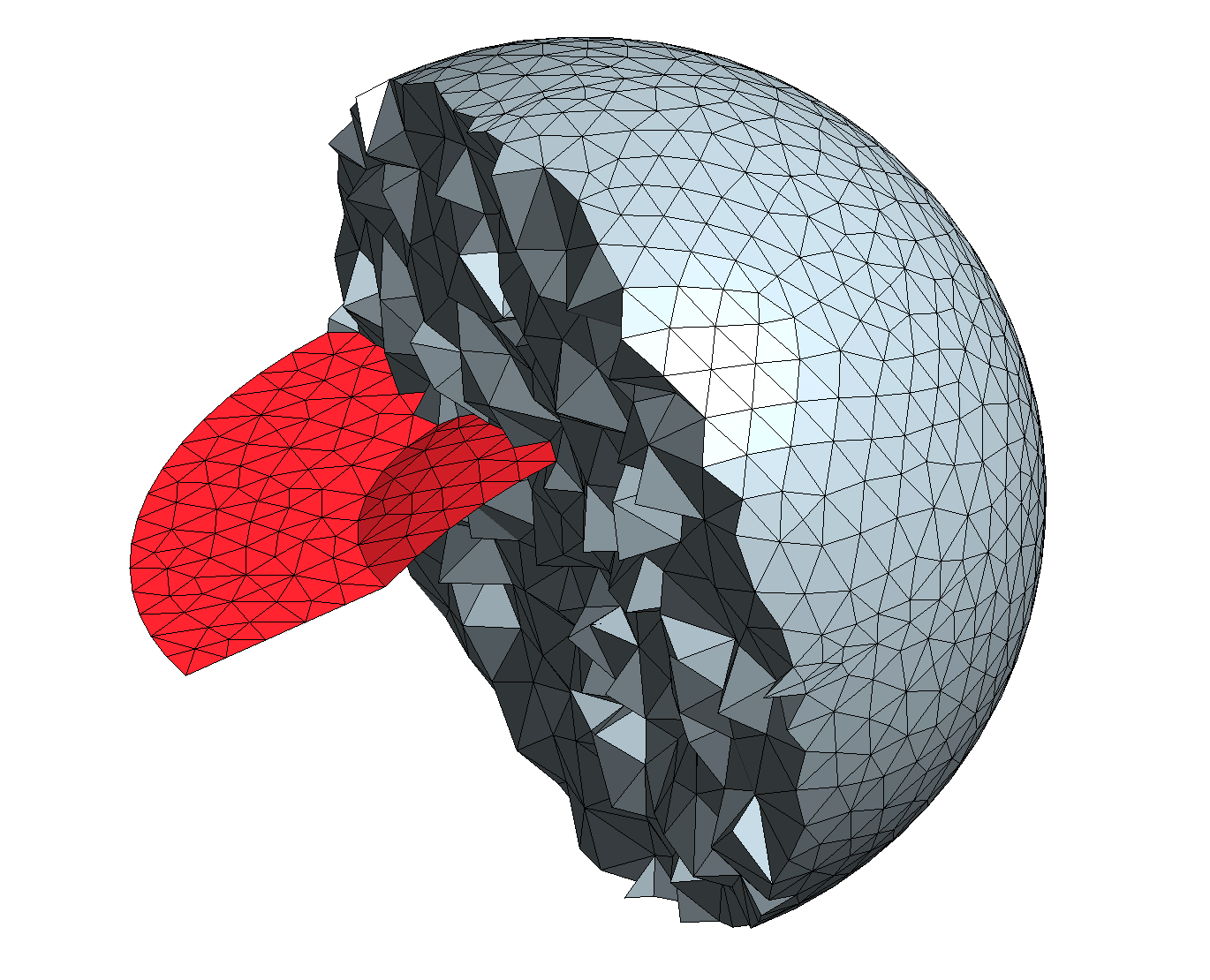
I have tried to extend my function to the whole domain (by a strictly positive constant value outside the ring) and applying the tutorial but that messes up the geometry in the domain as the tube walls disappear. I tried to add to the command line the option -opnbdy but the adapted level-set surface becomes not smooth for a reason I don’t understand.

Do you have any idea how I could achieve my goal ?

Regards,

Hugo Girardon.

Hi Hugo,

I have few questions:

  • Is it possible to attach few images of your input mesh and of the associated level-set function?
  • Your aim is to create explicitely the surface defined by the level-set 0 or to adapt the mesh to have more points / elements near this level-set?
  • Your domain is a volumic domain everywhere or do you have “floating” surfaces?

Thank you by advance for your answer,

Regards,
Algiane

Sure here are some images (I’m sorry I didn’t do it before, I was having trouble doing it)

My aim is to create explicitly the surface defined by the level-set 0, as I want to have a smooth interface.

My domain has several “floating” surfaces as you can see on the images below. The first picture is the domain mesh, the second is the level-set function defined on the sub-domain (level 0 is supposed to be here a portion of an ellipsoid).

I hope that everything’s clearer now, if you have any other question, please feel free to ask me.

Regards,

Hugo Girardon.

Edit : That might have been a poor choice of picture as it seems that the domain is 2D, my bad. Please keep in mind that it is a cylindrical 3D domain.

Hi,

Don’t worry for the images, I am used to Gmsh vizualisation.

By default, in level-set discretization mode, Mmg deletes all the domains of the mesh (it removes the tetra tags / references) and discretizes the two new domains defined by the level-set and as Mmg keeps only triangles if they are at the interfaces of two different domains, your cylinder is deleted.

It is planned to provide the possibility to keep the initial tags but not yet implemented (see this discussion).

Using the opnbdy option to overpass this lack was a good idea, just keep in mind that when it will be implemented, it will be more efficient and reliable to remap the input tag: the opnbdy option was created to allow to preserve a floating surface (so triangles between tetra of same tags) in case where the surface doesn’t define two different domains (see the attached picture).

I don’t know why the combination of the -ls and -opnbdy option fails (I will try to debug this as soon as possible). On my toy case the following tricks works:

  • discretizing the level-set (with mesh improvement disabled) first;
  • and improving the mesh in a second stage;
mmg3d_O3 -ls -opnbdy input.mesh -noinsert -noswap -nomove  tmp.mesh
mmg3d_O3 -opnbdy tmp.mesh output.mesh

I attach here the files of my toy test case.
input.mesh (758.5 KB) input.sol (61.2 KB)
output.mesh (410.2 KB)

I hope that it will helps,
Regards

Hi,

Sorry for the late answer, I will try to use your trick to do what I aim to do. In the meantime, another question has arisen. Here I am considering a simpler domain hereafter

The level-set does not matter (well I think it does not), let’s just assume it exists. After using the command :

mmg3d_O3 Meshes/MeshPhi.mesh -sol Fields/phi.sol -ls -nr -hmax 0.002

I obtain a new mesh (image below). The surface defined by level 0 of the level-set is smooth as expected. However, I do not if it’s visible enough on the image, but compared to the previous mesh, I observed that the boundary has changed, there are small “bumps”.

Why is that ? Is there a way to remove these unwanted irregularities ?

Regards,

Hugo.

Note : I do not know if I should create a new topic for that matter, but I can move that question should you think it’s appropriate.

Hi,

The bump are due to the -nr option I think: it disables the detection of sharp angles so Mmg tries to build a “regular” surface everywhere.
You can handle the sharp angle detection with the -ar option (it defaults to 45, by increasing this value, you detect fewer sharp angles)

(No need to move the topic now :wink: ).

Regards,

Algiane

Thanks a lot !

Have a nice day,

Hugo.

Sorry, I have one last question for you : what does the -nosurf for the implicit domain meshing ?

It is kind of transverse to mmg, but I am using the updated meshes in a FreeFEM code and it seems that when using the -nosurf option, the output mesh does not work well with FreeFEM functions (even though it “looks” fine on Gmsh).

As I said, it does have to do with FreeFEM that with mmg, but as I cannot wrap my mind around the problem, I thought you might be able to explain to me what is happening on the mmg side.

Regards,

Hugo.

Hi,

In implicit domain meshing mode, the -nosurf option tries to preserve the external surface of the input mesh:

  • If you start from a mesh that contains multiple domains, the interfaces between this domains are still deleted and the -nosurf option has no effects on its;
  • if your level-set intersects the external surface, intersecting elements are not preserved and are splitted to allow the level-set discretization.

So maybe freefem++ assumes that triangles are not modified in -nosurf mode and doesn’t update the triangle infos?

Regards,
Algiane