Meshing of a uniform tetrahedral mesh

Hi,

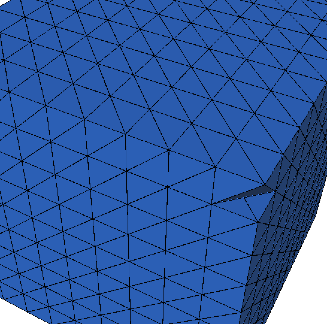
I’m trying to mesh a volumetric binary image. Since it doesn’t look like mmg3d supports the direct conversion of a binary image to a mesh, I tried to convert this image into a uniform tetrahedral mesh. In this mesh, each vertex represents a voxel of the original image. I also created a .sol file, which assigns the value of the voxels to the vertices and should represent a levelset function for mmg3d.

This is my input mesh:

input.mesh (79.9 KB)
input.sol (2.0 KB)

I now run mmg3d input output -ls 0.5 -nr -nosurf and get this result:

output.meshb (1.4 MB)
output.sol (227.5 KB)

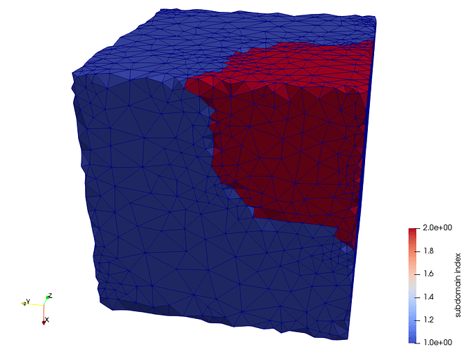
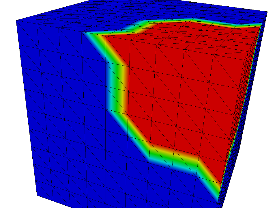
As you can see mmg3d detected the levelset and adjusted the mesh accordingly. What I was hoping is that mmg3d also remeshes those cubes from the input mesh, so that I get a nice looking mesh that looks similar to the examples on your website. I also tried to run mmg3d with the -optim option, but the cubes from the input mesh are still visible.

Is it possible to create a nice looking mesh for this kind of input mesh using mmg3d?

Best regards,
Max

Edit:
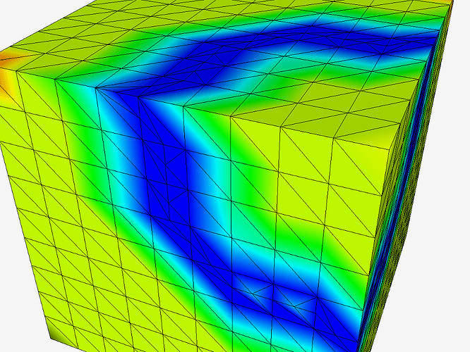
Here is an example of what I would like the mesh to look like. I created this example using cgal and it is almost what I want. As you can see the cube structure from the input image is gone and the net is coarser where there are not so many details and more detailed at the intersection of two domains. The only thing that makes it not suitable for me is that the outside surface is not smooth. If mmg3d can make the surface of such a mesh smooth, that would also be an option.

Hello Max,

I think the files attached are not the right ones :
the mesh contained in input.mesh seems not conform…

By the way, with -nosurf option, you impose to mmg3d to not touch your boundaries : the remeshing of your boundaries is avoid…

You can try to remove this option and see if your result is better.

Best regards,

Cécile

Hello Cécile,

thanks for your answer. What do you mean by “not conform”? I can both show the mesh in medit and process it with mmg3d. But I generated the mesh myself, so there may be issues, because I didn’t find a good documentation on the format. (For example the meaning of the refid s.) I already tried to run mmg3d without the -nosurf option, but the mesh didn’t get better and I had some additional issues with the corners not being kept.

Best regards,
Max

Hello Max,

By non-conformal, Cécile means that we think that your mesh contains overlapping elements.

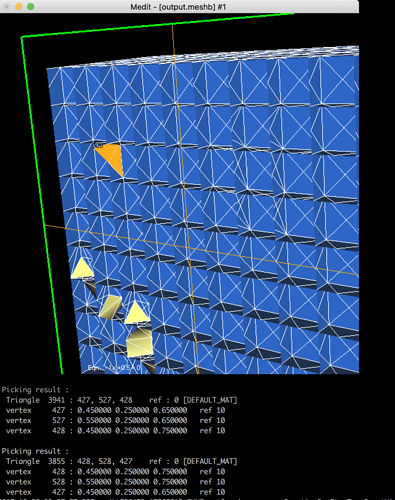
For exemple, with medit, if I cut the mesh (‘F1’) and print only the triangles (‘F4’). I can pick the triangle 3941 (‘shift + left click’) and see it vertices on the terminal (427-527-428) by clicking again in the same area, I can find an overlapping element (triangle 3855 with vertices 428-528-427, in orange on the attached picture).

I am not sure because it is harder to visualize but I think that you have the same problem on you tetrahedra.

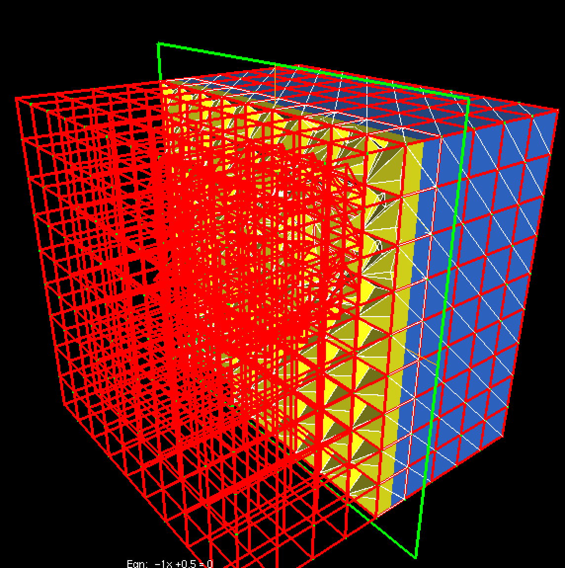
Mmg doesn’t detect the non-conformity but it detects non-manifold areas in your mesh, thus it adds ridges and required vertices everwhere (red edges and green vertices in the picture below (‘g’ with medit)) and mmg is unable to modify your mesh.

To create your mesh, you can:

  1. create directly an medit file. The file format is documentated here https://www.ljll.math.upmc.fr/frey/logiciels/Docmedit.dir/Docmedit.html#SECTION00031000000000000000. Some useful infos:

    • The ref field is used the set different colors on the elements/boundaries. For example, if you have a mesh with 2 domains, the tetras of the first domain will have the same ref (1 for example) and the tetra of the second domain a different one (2 for exemple). You may also have only 1 domain (your cube) but various boundary conditions over the different faces of the domain. In this case, you will associate a given ref to each face (a set of triangles) of the domain in order to be able to apply your boundary conditions. For now, the ref field of points are not used in Mmg. You must keep in mind that Mmg will try to preserve the underlying geometry of each domain with a given ref.
  • It is not mandatory to specify triangles in your tetrahedral mesh if you don’t have to impose a specific ref field over your boundaries. Mmg will automatically build the boundary triangles from the mesh tetrahedra.

  • If you need to provide boundary references, give only the boundary triangles and not the internal ones (triangles at the interface between tetrahedra of same refs). The internal triangles are useless and erased by Mmg.

  1. Use the gmsh file format if you feel more confortable. Mmg is able to read it (and convert it at the medit file format).

I hope that it will help you.

Best Regards,

Algiane

Hey Algiane,

that is very helpful, thank you. I’m going to double check the mesh generation but I still have a question:

The input mesh that I generated doesn’t contain any triangles at all, only vertices and tetrahedra, therefore I wonder why I get overlapping ones?

My current input mesh generator creates for every 8 vertices, that correspond to the pixels

  • (x, y, z)
  • (x, y, z + 1)
  • (x, y + 1, z)
  • (x, y + 1, z + 1)
  • (x + 1, y, z)
  • (x + 1, y, z + 1)
  • (x + 1, y + 1, z)
  • (x + 1, y + 1, z + 1)
    five tetrahedra filling the space between them according to https://www.ics.uci.edu/~eppstein/projects/tetra. Can an error in this procedure result in overlapping triangles, even though no triangles are created?

Sorry that this question isn’t actually mmg3d specific.

Best regards,
Max

I haven’t take care that you don’t have input triangles : it means that medit has build the triangles from your tetrahedra (it build a triangle if it is not shared by 2 tetra. In your case, it confirms that your mesh is non-conformal).

Your splitting of 1 pixel into 5 tetra works but the square face shared by 2 adjacent pixels is splitted along a different diagonal depending on the pixel from which you see the face. I join a picture but I don’t know if it is clear (I just remove 1 tetra on the bottom corner of 1 pixel and we can see that the pixel just below is splitted differently).

Regards,

Algiane

Thank you so much, I haven’t thought about that. With that issue fixed,

input.mesh (79.9 KB)

the results are now much better (with an additonal -optim) pass. There are still some cubes visible but I think that can now be fixed by playing with the parameters.

Best regards,
Max