Surface mesh from a triangulated CAD model

Dear all,

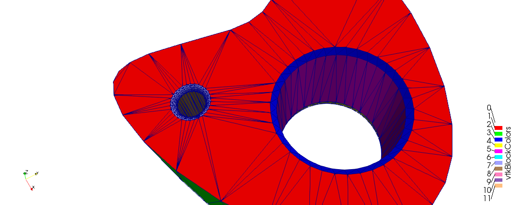
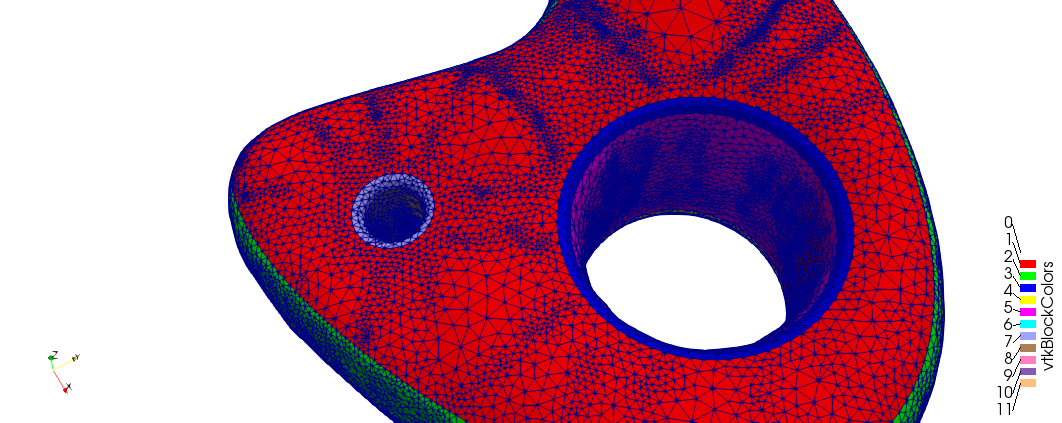
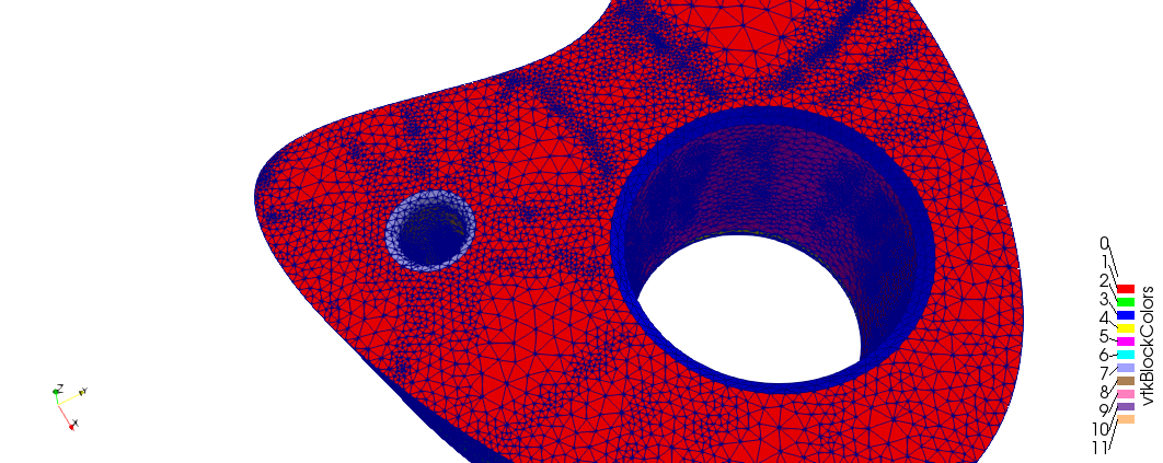
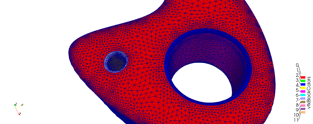
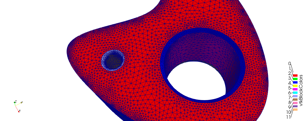
I’d like to use mmgs to build a surface mesh to use for computations from an stl-like triangulation that looks like this.


(I think my problem is quite similar to the Mesh decimation example on the website)

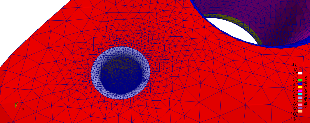
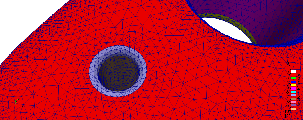
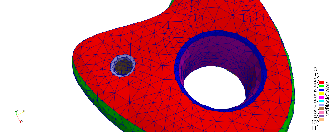
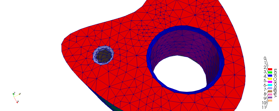
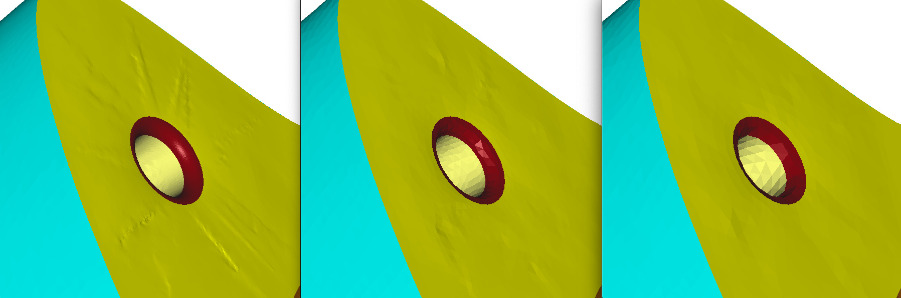
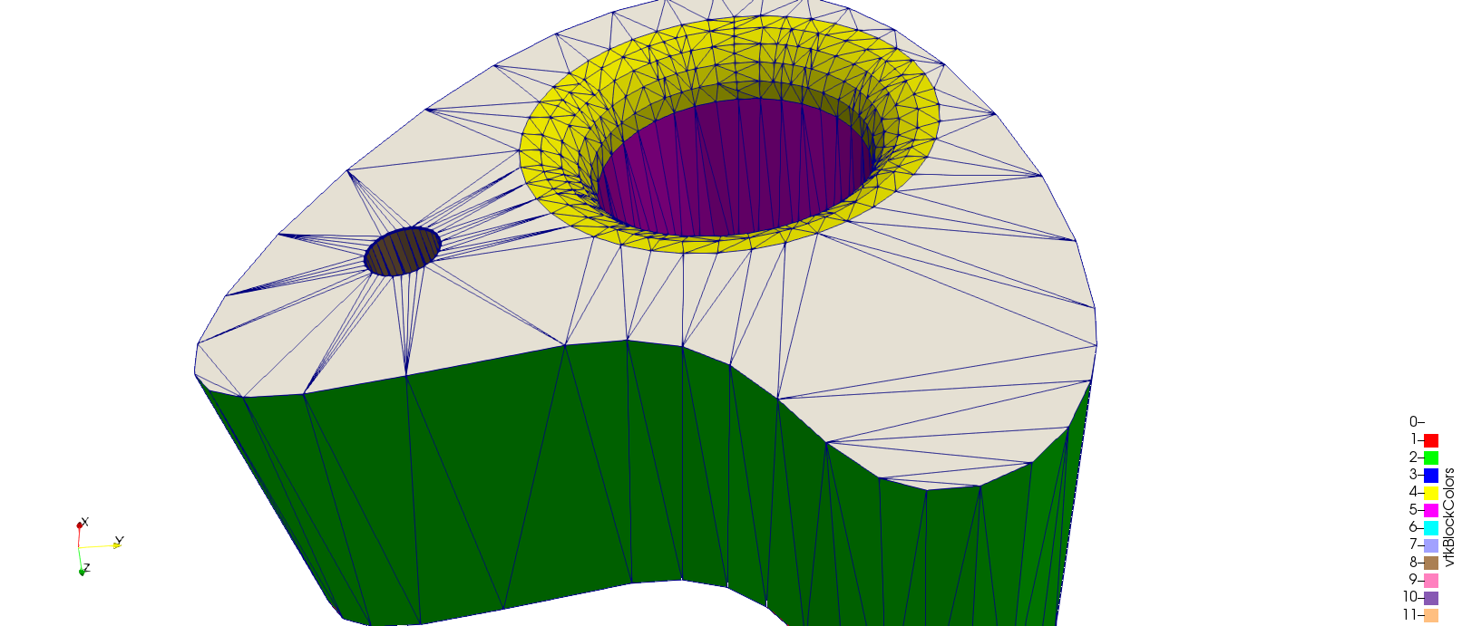
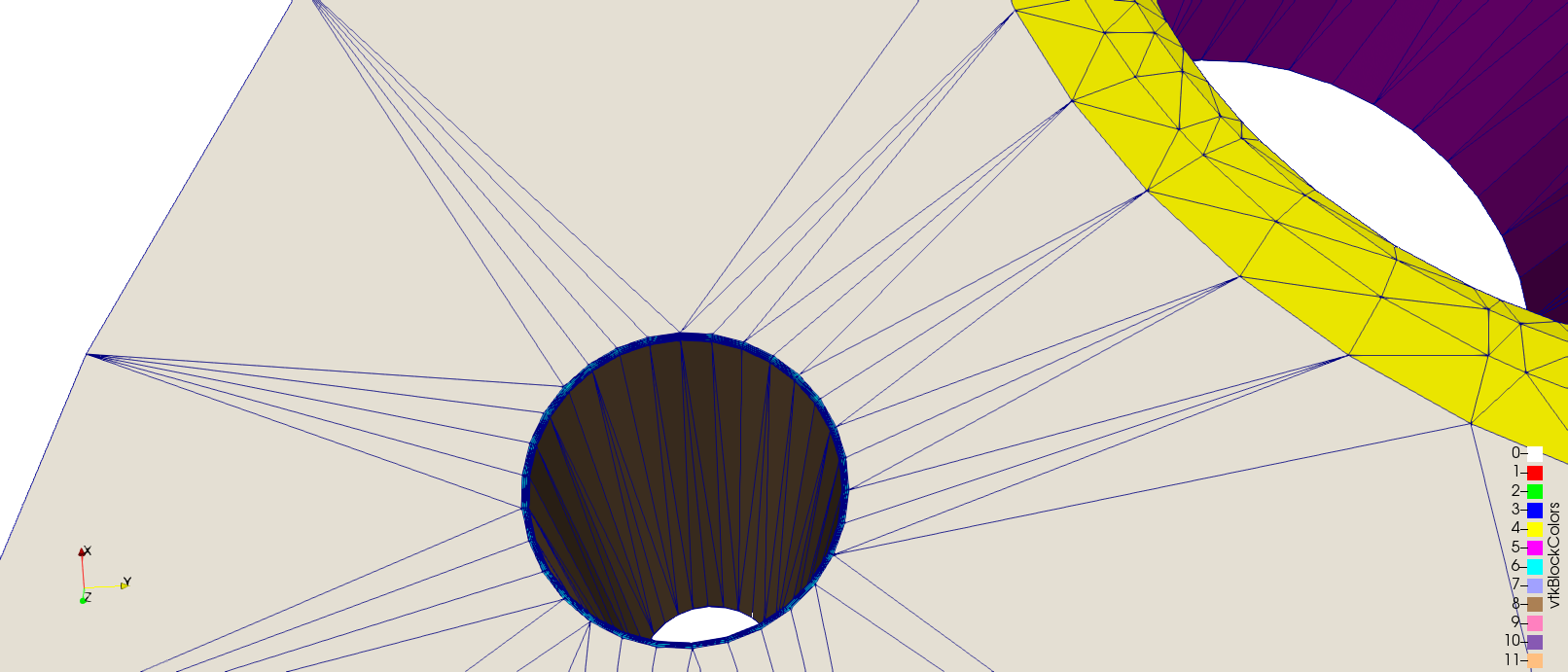
For this, I prescribe an isotropic metric which, at any point is the length of the smallest edge containing this point. This mostly works well (if I re-project on the CAD model after at least), except in areas like the cylindrical hole in the second image. Indeed, the mesh is much too fine in the while cylinder, it is not only refined in the fillets.

I was thinking about splitting all the triangles in the stl-like triangulation before calling mmsg to avoir having long edges with small cells at both sides. Is is possible with mmg or should I do it by hand? Is there a better solution, how did you proceed for your example?

Thank you

Xavier

Hello Xavier,

If I understand your problem, you obtain a bad approximation of the inside surface of the cylinder?

If yes, you’re right, a “flat” split of the triangles of this surface will very probably solve the problem. It is not yet possible in Mmg but I would like to add this possibility (I just don’t have the time right now, so I can give a deadline for this): is it an urgent need?

Best Regards,

Algiane

Thank you

My problem is that the mesh is too fine inside the cylinder.


I can always perform a second remeshing operation to get rid of the small triangles

But the overall process is slow.

I’ll try to split the triangles by hand and let you know. There is no urgent need!

Ok, I didn’t understand your problem!

The very small triangles may have 2 origins :

  • the hausdorff parameter (maybe you need to increase it, by default its value is 0.01) and as it aims to keep the discretization close to the smooth surface, it may leads to insert lot of points in curfe areas;
  • the input metric (but I don’t think so because the smallest edges are along the sharp angle of the cylinder and they seems largest than in your output mesh).

A simple test the hausdorff parameter influence may be to run the remesher without any metric : in this case, Mmg is it able to unrefine the cylinder?

Still : are you providing the same metric between step 1 and 2 or are you recomputed it from the output mesh of the step 1? (I still don’t understand why Mmg can generate such different meshes…).

In fact, I am not sure now than splitting the triangles will help: what is your idea about that?

Regards,

Algiane

Regards

If I try to call mmgs with a large value of the metric, relying on hausd to refine the mesh in curved areas this is what I get:

This is why I tried to use the size information in my initial mesh to prescribe the metric.

However, if I try to decrease hausd gradually the results are better

The different colors correspond to different triangle tags. How can I avoid smoothing at the interface between different surface tags to get a better mesh at the red-green interface (where I have a 90° angle)

Thank you

Ok!

I have upgraded your status : does it work better now?

So :

  • your idea of splitting the initial stl mesh is definitively a good idea : the surface model that mmg reconstructs is false because the initial mesh doesn’t have “internal” vertices on the surfaces (for example, the red plane became curved);
  • to unrefine, you will need to increase the hausdorff parameter (as you have just done);
  • Normally, Mmg detects automatically sharp angles of the geometry, here it seems that it fails to do it. I will investigate and I will get back to you.

Regards,

Algiane

Hello Xavier,

I can’t figure out why Mmg doesn’t detect your sharp edges. Is it possible to send me your mesh, either here, either by private message?

Thank you by advance,
Regards,

Algiane

Hi Algiane,

Here are the mesh / sol before and after adaptation.
geom_1.zip (2.4 MB)

I use h = 1, hgrad=1.5 et hausd=0.1
To import the mesh, I use:<a class=“attachment”

MMGS_Init_mesh(MMG5_ARG_start,
               MMG5_ARG_ppMesh, &pmesh, MMG5_ARG_ppMet, &psol,
               MMG5_ARG_end);

if ( MMGS_Set_meshSize(pmesh, n_nodes, n_tris, n_edgs) != 1 )  exit(EXIT_FAILURE);

for(int i = 0; i < n_nodes; i++)
    if ( MMGS_Set_vertex(pmesh, xyz[3*i+0], xyz[3*i+1], xyz[3*i+2], node_tags[i], i+1) != 1 )  exit(EXIT_FAILURE);

for(int i = 0; i < n_edgs; i++)
    if ( MMGS_Set_edge(pmesh, edgs[2*i+0]+1, edgs[2*i+1]+1, edg_tags[i]+1, i+1) != 1 )  exit(EXIT_FAILURE);

for(int i = 0; i < n_tris; i++)
    if ( MMGS_Set_triangle(pmesh, tris[3*i+0]+1, tris[3*i+1]+1, tris[3*i+2]+1, tri_tags[i]+1, i+1) != 1 )  exit(EXIT_FAILURE);

if ( MMGS_Set_solSize(pmesh, psol, MMG5_Vertex, n_nodes, MMG5_Scalar) != 1 )
    exit(EXIT_FAILURE);

Thank you for your help.
Best regards,

Xavier

Hi,

Here is an update. If I set the corner and ridges manually

for(int i = 0; i < n_nodes; i++){
    if ( MMGS_Set_vertex(pmesh, xyz[3*i+0], xyz[3*i+1], xyz[3*i+2], node_tags[i], i+1) != 1 )  exit(EXIT_FAILURE);
    if (node_tags[i] > 0)
        if (MMGS_Set_corner(pmesh, i) != 1 )  exit(EXIT_FAILURE);
}

for(int i = 0; i < n_edgs; i++){
    if ( MMGS_Set_edge(pmesh, edgs[2*i+0]+1, edgs[2*i+1]+1, edg_tags[i]+1, i+1) != 1 )  exit(EXIT_FAILURE);
    if (edg_tags[i] > 0)
        if (MMGS_Set_ridge(pmesh, i) != 1 )  exit(EXIT_FAILURE);
}

everything works fine. I thought edges belonging to 2 triangles with different tags were automatically tagged as ridges (and similarly for corners), my mistake!

Thank you for your help (and your library!)

Xavier

Hi Xavier,

Great news, I was not able to reproduce the “non-detected” sharp angles and I was totally stumped in finding the error :-D.

Just few remarks on your testcase (but you are probably already aware of that):

  • if you want to provide a constant metric (eg. 1.0), you can use the -hsiz option (or MMGS_DPARAM_hsiz keyword) : mmgs_O3 inputmesh.mesh -hsiz 1 ;
  • Even with the sharp angles detection, as your input mesh doesn’t have “inside” nodes on certain surfaces, the reconstruction of the ideal geometry is very poor:
    • the better way to handle that is to have a “flat” cut of the triangles before calling Mmg;
    • another way (but your surface will keep some bumps) is to set a large hausdorff (so we don’t ask to stay close from the geometry and the surface model is less sensitive) and to use only the sizemap to control the edge sizes. I add the picture of the surface approximation obtained with a hausdorff of 0.01, 0.1 and 1 (the sizemap is the same (1) for the 3 tests).

Regards,

Algiane